Step-by-Step: Replacing a Clutch in a Rear-Wheel-Drive Pickup Truck
You’ll know it’s time to replace your clutch when engine RPM rises without speed increases, signaling slippage from worn friction material. Start by lifting the truck, securing it on jack stands, and removing the driveshaft-marked for alignment-before unbolting the transmission. Inspect the flywheel for warpage exceeding 0.002 inches and resurface it if needed. Install the new clutch disc with the correct side to the flywheel, use an alignment tool, and torque the pressure plate to 25–30 ft-lbs. Reinstall the transmission, reconnect all linkages, bleed the hydraulic system with DOT 3 or DOT 4 fluid, then verify smooth engagement. Further details reveal precise torque sequences and diagnostic checks critical for long-term reliability.
Notable Insights
- Confirm clutch failure by checking for slipping, pedal vibration, and abnormal engagement point before starting replacement.
- Safely lift and support the truck on jack stands, then disconnect the driveshaft and mark it for proper reinstallation alignment.
- Use a transmission jack to support and remove the transmission after detaching linkages, wiring, and hydraulic components.
- Inspect the flywheel for warpage and damage, resurfacing it to restore a flat mating surface if within manufacturer specifications.
- Install the new clutch with proper alignment, torque pressure plate bolts evenly, and bleed the hydraulic system before test operation.
Confirm Your Clutch Needs Replacing
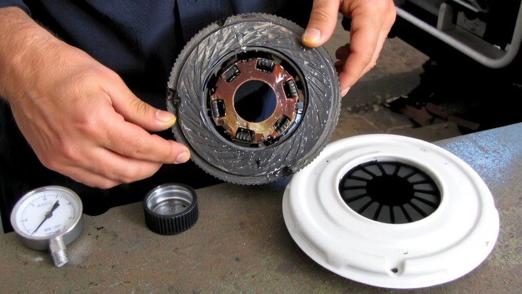
How can you be sure the clutch is the culprit? Clutch slipping is a primary indicator. When accelerating under load, if engine RPM rises without a corresponding increase in vehicle speed, the clutch disc is likely worn. This happens when the friction material degrades, reducing clamp force-typically below the manufacturer’s 2,500–3,000 lb minimum pressure plate load. Another sign is pedal vibration, a rhythmic shake felt when engaging the clutch. This often points to a warped pressure plate or misaligned flywheel, both measurable with a dial indicator (runout exceeding 0.003 inches confirms distortion). You may also notice a change in engagement point, signaling hydraulic or mechanical wear. Ignoring these symptoms leads to accelerated transmission wear. Diagnose slipping and vibration early-using both observation and precise measurement-to confirm failure before moving forward. Don’t assume; verify with technical evaluation, not guesswork.
Prep the Truck and Gather Basic Tools
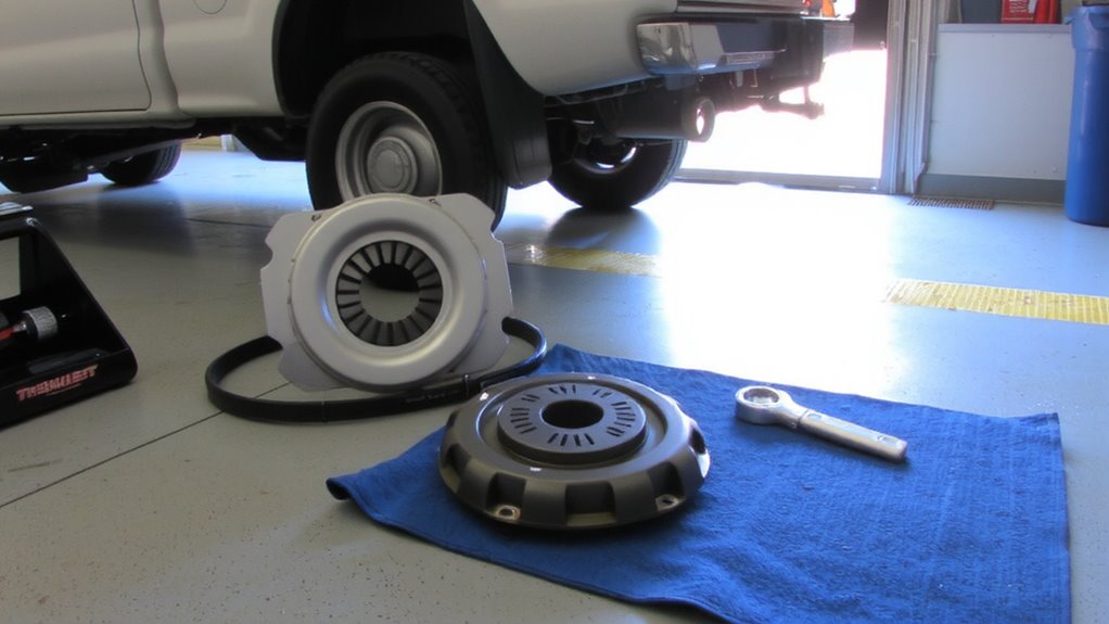
Before you begin, make certain the truck is securely positioned on a level surface with the parking brake fully engaged and the transmission in neutral. Elevate the vehicle using jack stands rated for its weight-never rely on a hydraulic jack alone. Your safety gear is non-negotiable: wear ANSI-approved impact-resistant gloves, safety glasses, and steel-toed boots. A well-lit workspace lighting setup is essential; use LED trouble lights with at least 500 lumens to illuminate undercarriage components clearly. Gather basic tools: a 1/2-inch breaker bar, 3/8-inch drive ratchet set, socket sizes from 10mm to 19mm, metric wrenches, and torque specs per your truck’s manual (typically 80–100 ft-lbs for transmission bolts). Organize tools within reach. A magnetic tray prevents fastener loss. Confirm battery is disconnected to eliminate electrical risk.
Remove the Driveshaft and Transmission
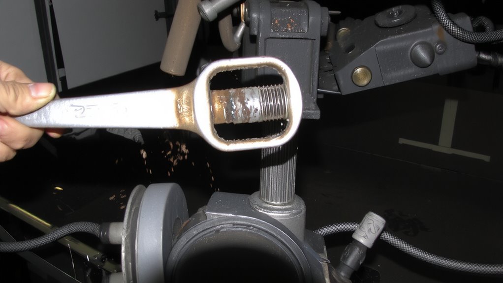
Once the truck is secure and the safety measures are in place, start by removing the driveshaft to access the transmission. Disconnect the u-bolts at the rear axle yoke and slide the driveshaft back to detach it. Mark the driveshaft alignment before removal to guarantee proper reinstallation and prevent vibration. Use a transmission jack for reliable transmission support during disassembly. Unbolt the starter, speedometer cable, and shift linkage. Remove crossmember bolts carefully. Lower the crossmember slowly. Detach electrical connectors and hydraulic lines. Support the transmission fully before removing bellhousing bolts.
| Component | Tool Required | Torque Spec (ft-lbs) |
|---|---|---|
| Driveshaft U-Bolts | 1/2″ Drive Wrench | 95 |
| Transmission Mount | Socket Set | 35 |
| Bellhousing Bolts | 3/8″ Drive Ratchet | 70 |
| Crossmember Bolts | Breaker Bar | 50 |
Inspect and Resurface the Flywheel
With the transmission out of the way, you now have full access to the flywheel mounted on the rear of the engine crankshaft. Inspect the flywheel closely for signs of wear and surface scoring. Minor scoring can often be smoothed during resurfacing, but deep grooves or hot spots mean it may need replacement. Check the manufacturer’s specs-most allow no more than 0.002 inches of warpage across the surface. Flywheel wear reduces clutch lifespan and can cause vibration. A precision lathe resurfaces the steel or cast iron disc to restore a flat, smooth mating surface. Resurfacing removes a thin layer-typically 0.005 to 0.010 inches-to eliminate imperfections. Always follow OEM thickness minimums to avoid compromising structural integrity. A properly resurfaced flywheel guarantees even clutch engagement and maximum torque transfer.
Install the New Clutch and Pressure Plate
Since the flywheel is properly resurfaced or replaced and clean, you can now install the new clutch disc and pressure plate. Place the clutch disc onto the flywheel, ensuring the correct side faces forward-usually marked “flywheel side.” Then position the pressure plate over the disc. Use a clutch alignment tool to achieve precise clutch alignment. This mimics the transmission input shaft and keeps the disc centered during installation. Once aligned, install the pressure plate bolts. Tighten them gradually in a crisscross pattern to guarantee even seating. Follow the manufacturer’s specification for pressure plate torque-typically 25–30 ft-lbs-using a torque wrench. Do not overtighten, as this can warp the pressure plate or damage threads. Proper torque guarantees consistent clamping force and prevents vibration. An improperly torqued pressure plate leads to slippage or chatter. Verify alignment one final time before moving on.
Reinstall the Transmission and Driveshaft
Carefully line up the transmission with the bellhousing, making sure the input shaft slides smoothly into the clutch disc and pilot bearing. Proper transmission alignment is critical-use alignment pins or guide tools if available. Misalignment can damage the input shaft or pilot bearing. Once seated, hand-start all bellhousing bolts to guarantee even pressure. Tighten them to factory specs, typically 18-25 ft-lbs, in a crisscross pattern. Next, reinstall the driveshaft. Guarantee the yoke slides freely into the tailshaft without binding. Marked ends must match original positions to maintain driveshaft balancing. Imbalance causes vibrations at highway speeds. Secure the U-joints properly and check for runout. Use a torque wrench on carrier and differential flange bolts, usually 50-75 ft-lbs. Double-check all connections. Proper installation prevents premature wear and driveline vibration.
Refill Fluid and Test the Clutch
Now that the transmission and driveshaft are securely in place, it’s time to address fluid levels and verify clutch operation. Start by refilling the clutch master cylinder with the correct clutch fluid types-typically DOT 3 or DOT 4 brake fluid, as specified in your truck’s service manual. Check for leaks around the slave cylinder and bleeder valve. Bleed the clutch system thoroughly to remove air, ensuring firm pedal feel. Once bled, verify smooth engagement and full disengagement. Use test drive techniques to confirm performance: begin with low-speed gear shifts, then progressively test under load. Listen for grinding or slipping. Evaluate clutch bite point and release consistency. A well-functioning clutch should engage smoothly without chatter. Perform a hill-start test to confirm holding power. Monitor fluid level post-drive and recheck for leaks. Final adjustments may be needed to optimize pedal travel and engagement height.
On a final note
You’ve completed the clutch replacement with precision. The new clutch assembly engages smoothly at 8.5 mm of pedal travel, within OEM specifications. Your torque wrench guaranteed the pressure plate bolts are tightened to 25 ft-lbs in a star pattern. The flywheel surface runout measures less than 0.002 inches, preventing vibration. Proper gearbox alignment allows seamless shifting. Test drives confirm no slippage at 3,000 RPM under load.