Testing for Power and Ground at a Fuel Injector Connector
You’ll need a digital multimeter with at least 10 MΩ impedance and sharp, insulated test leads. Locate the injector connector on the intake manifold or cylinder head. With the ignition on and engine off, backprobe the power wire-expect 12 to 14 volts. Use an oscilloscope to check the ECU ground pulse on the signal wire; a clean downward pulse confirms control. Low voltage or a missing pulse points to wiring faults or ECU issues. Ground resistance should be under 0.1 ohms. Corrosion or loose terminals cause voltage drops. Fix damaged wires, clean connections, and retest. Further diagnostics reveal deeper system performance insights.
Notable Insights
- Confirm battery voltage is 12.6V or higher before testing power and ground at the injector connector.
- Use a digital multimeter to backprobe the power wire with ignition ON, engine OFF, expecting 12–14V.
- Locate the fuel injector connector on the intake manifold or cylinder head, depending on injection type.
- Test the ground circuit resistance to ensure it is below 0.1 ohms to prevent control issues.
- Check for a clean ECU ground pulse using an oscilloscope on the signal wire during engine operation.
Gather Your Tools
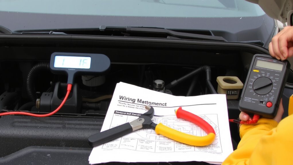
You’ll need a few essential tools to accurately test power and ground at a fuel injector connector. A digital multimeter is critical-use one with at least 10 MΩ impedance to avoid loading the circuit. Test leads should have sharp, insulated probes for precise contact. You’ll also need a terminal release tool compatible with your vehicle’s connector style. Your fuel type and engine displacement determine injector specifications, so consult the service manual for expected voltage and resistance values. Gasoline direct injection systems often require tighter tolerances than port injection. For larger engine displacement engines, higher current demands mean even minor voltage drops can affect performance. Always verify battery voltage before testing-anything below 12.6V may skew results. Use dielectric grease on connectors after testing to prevent corrosion. Safety glasses and insulated gloves are required-live circuits carry risk.
Locate the Fuel Injector Connector
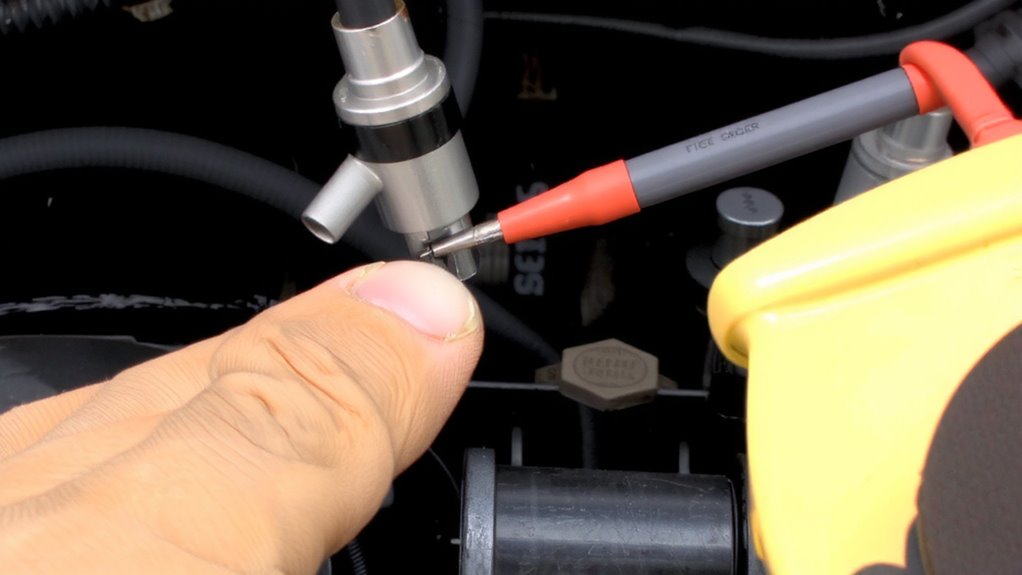
| Injector Type | Typical Connector Location |
|---|---|
| Port Fuel | Intake manifold, near valve cover |
| Direct Fuel | Cylinder head, close to spark plugs |
| Throttle Body | Top of throttle body assembly |
| Sequential | Aligned with each cylinder port |
| Multi-Point | Along intake runners |
Use a flashlight and mechanics mirror if visibility is limited. Confirm wiring harness integrity before proceeding.
Test for Power at the Injector
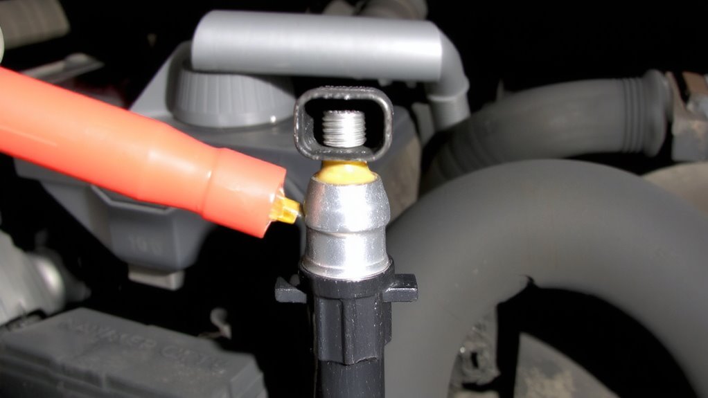
After locating the fuel injector connector, begin testing for power using a digital multimeter set to measure DC voltage. Backprobe the power wire-usually red or red/white-while the ignition is ON but the engine is OFF. You should read 12 to 14 volts, matching battery voltage. This power supply is essential because fuel injectors are solenoid-operated valves requiring consistent voltage to open and deliver fuel. Without proper power, fuel pressure won’t matter since the injector can’t activate. Correct ignition timing depends on precise fuel delivery, which starts with injector operation. Voltage drops below 11 volts may indicate wiring resistance or a weak circuit, disrupting performance. Verify your multimeter leads make solid contact and verify readings across all injectors. Consistent voltage confirms the power side is functional-critical for synchronized engine operation. Never assume power exists; always test. This step precedes checking the ECU ground signal. For accurate results, use a digital multimeter with auto-ranging capability and a high impedance input.
Check for ECU Ground Pulse
How does the fuel injector actually fire? The ECU triggers it by grounding the control circuit. To verify this, back-probe the low-side signal wire with your scope while the engine runs. You should see a clean injector waveform-each downward pulse is the ECU activating the injector. A missing or irregular pulse means the ECU isn’t commanding properly or there’s a wiring fault. Look for crisp edges and consistent timing; poor signal integrity distorts the waveform, causing misfires or lean conditions. Use a known-good cylinder for comparison. Typical pulse widths range from 2–6 ms at idle, depending on engine load and temperature. Confirm the ground pulse frequency matches engine speed-one pulse per cycle in sequential systems. If the waveform is flat, check ECU output, driver circuits, and wiring continuity. Signal integrity is critical: noise or attenuation suggests damaged harnesses or ECU issues.
What Your Readings Mean
You’ve confirmed the ECU sends a ground pulse to trigger the injector, but now it’s time to interpret what your scope and meter readings actually tell you about system health. A clean, sharp pulse indicates proper ECU control; jagged edges or inconsistent waveforms suggest signal interference. Voltage drop across the power side should be less than 0.2V-if higher, resistance in the circuit is starving the injector. Stable 12V supply confirms adequate power; fluctuating voltage points to weak connections.
| Reading Type | What It Means |
|---|---|
| High voltage drop | Excessive resistance, poor connection |
| Irregular pulse | Signal interference or ECU issue |
| Low supply voltage | Faulty power feed or damaged wiring |
These measurements reveal hidden faults before they cause misfires or stalling.
Fix Common Power and Ground Issues
A solid connection makes all the difference when diagnosing fuel injector performance. You must guarantee power and ground circuits are clean and tight. Corroded or loose terminals cause voltage drops, leading to misfires or poor injector response. Check the connector pins for bent or damaged leads-replace any with visible wear. High resistance in the ground path often stems from degraded wiring insulation or faulty splices. Repair these with heat-shrink connectors, not electrical tape. Fuel contamination accelerates injector wear, leaving deposits that clog nozzles and disrupt spray patterns. Flush the system and inspect for debris in the fuel rail. Use a multimeter to verify 12+ volts at the injector harness with the key on. Grounds should read less than 0.1 ohms. Addressing these issues restores proper pulse width and atomization, critical for combustion efficiency and emission control.
On a final note
You now know how to verify power and ground at a fuel injector connector. Always see 12V on the power wire with the key on. The ground signal comes as a rapid pulse from the ECU, visible with a test light or multimeter. No power means a wiring or fuse issue. No pulse suggests an ECU or driver problem. Use precise diagnostics to fix the root cause fast.