Oxygen Sensor Boss Thread Repair Using Time-Sert Inserts – Procedure Walkthrough
You start by inspecting the 18mm oxygen sensor boss for damage, checking threads with a pitch gauge and looking for corrosion. Remove the old sensor with a specialty socket, then clean the bore thoroughly. Drill precisely to 10.2 mm using a guide and cutting fluid. Tap to 12×1.5 mm at 16–18 mm depth. Install the 17-4 PH stainless Time-Sert insert flush with the surface. Torque the new sensor to 30–50 N·m. Proper setup guarantees long-term reliability under extreme exhaust conditions. This method restores full thread strength and prepares the system for peak sensor performance.
Notable Insights
- Assess thread damage and corrosion in the oxygen sensor boss before starting repair.
- Remove the oxygen sensor carefully using a proper socket and penetrating oil to avoid further damage.
- Clean and measure the threaded hole to ensure it’s free of debris and within spec.
- Drill with a 10.2 mm bit and tap to 12×1.5 mm for proper Time-Sert insert fitment.
- Install the Time-Sert insert with a mandrel, then reinstall the sensor with anti-seize and proper torque.
Check the Damage to the Oxygen Sensor Boss
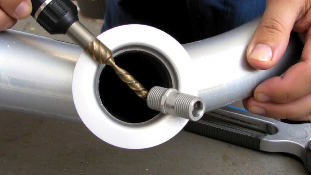
Damage to the oxygen sensor boss often starts with stripped threads, a common issue when the sensor is improperly installed or removed without proper tools. You must assess thread integrity immediately to determine repair feasibility. Inspect the bore for distortions using a thread pitch gauge; damaged threads often show misalignment or galling. Corrosion assessment is critical-look for pitting or oxidation, especially in aluminum exhaust manifolds exposed to moisture. Surface rust compromises material strength and insert adhesion. Use a bore scope if available to check internal damage. The boss typically measures 18mm outer diameter with M18x1.5 threads; any deviation beyond 0.15mm ovality requires repair. Aluminum housings are more prone to thread stripping than cast iron. Proper inspection guarantees the Time-Sert insert will seat correctly. Evaluate both mechanical wear and chemical degradation before proceeding. Accurate diagnosis prevents premature insert failure.
Remove the Damaged Oxygen Sensor
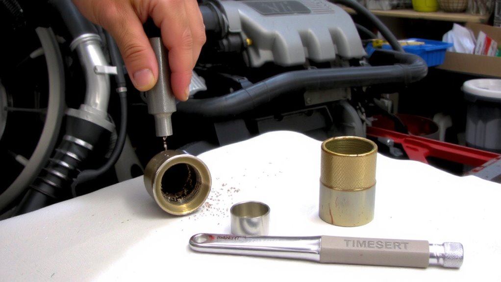
You’ll need the right tools and technique to safely remove the damaged oxygen sensor without worsening the thread condition. Use a high-quality oxygen sensor socket or crowfoot wrench to guarantee full contact with the sensor’s body during sensor removal. Apply penetrating oil to the sensor’s base and let it soak for 10–15 minutes to break down corrosion. Carefully turn the sensor counterclockwise with steady, even pressure-avoid jerking motions that could further damage the threads. If resistance is high, gently rock the sensor back and forth to loosen it. Once removed, perform a close visual boss inspection to assess the extent of thread damage. Do not probe deeply yet-reserve detailed evaluation until after cleaning. Proper removal preserves remaining threads for accurate assessment and guarantees compatibility with the Time-Sert repair kit specifications.
Clean and Measure the Stripped Thread Hole
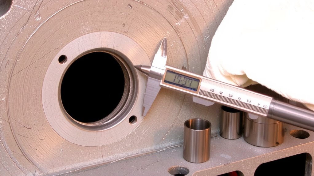
Start by thoroughly cleaning the threaded hole to remove all debris, oil, and corrosion that could interfere with accurate measurement and repair. Use a precision wire brush or thread chaser to restore the original thread depth without altering the hole’s diameter. Any contaminants left in the hole can compromise the Time-Sert insert fit and final surface finish. Inspect the bore with a bright light and magnifier to confirm cleanliness. Measure the existing thread depth with a depth gauge or machinist’s scale-most oxygen sensor bosses have a standard thread depth of 12–15 mm. Record this measurement to guarantee the drill depth for the Time-Sert won’t exceed the parent material’s limits. A smooth, uniform surface finish around the hole entrance prevents galling and ensures proper insert seating. Accuracy here directly affects installation success and long-term sensor reliability.
Drill and Tap for the Time-Sert Insert
Once the threaded hole is clean and properly measured, proceed to drill with a 10.2 mm (0.402 in) high-speed steel or cobalt bit to prepare for the Time-Sert 12×1.5 mm insert. Proper drill alignment is critical-use a center punch to mark the hole and a drill guide to maintain perpendicularity. Misalignment can compromise threads or damage surrounding material. Drill slowly, applying steady pressure to avoid bit wandering or work hardening. Use cutting oil to lubricate and extend bit life. After drilling, inspect the hole for burrs and remove them with a deburring tool. Next, tap the hole using a 12×1.5 mm tap. Control tap depth precisely-typically 16 to 18 mm-guaranteeing full thread engagement without exceeding the insert length. Use a depth gauge or marked tap to verify. Proper tap depth guarantees the Time-Sert installs flush and functions correctly.
Install the Time-Sert Repair Insert
While alignment and preparation are critical up front, the actual installation of the Time-Sert repair insert hinges on precise execution. You must use the correct Installation techniques to guarantee a secure fit. Start by threading the insert onto the provided installation mandrel-this tool aligns the insert straight into the tapped hole. Insert materials, typically 17-4 PH stainless steel, offer high strength and corrosion resistance, critical for exhaust system durability. Carefully screw the insert into the boss using steady, even pressure. The tapered design seats the coils tightly as they compress during installation. Continue until the top of the insert sits flush with or slightly below the casting surface. Do not over-tighten, as this can distort the threads. Proper seating guarantees load distribution across all coils. The mandrel allows control and prevents cross-threading. This method restores original thread integrity with a repair designed to last the life of the vehicle.
Reinstall the Oxygen Sensor
Now that the Time-Sert insert is properly seated and flush with the surface, you can reinstall the oxygen sensor with confidence. Guarantee oxygen sensor compatibility by verifying the sensor’s thread size, pitch, and heater circuit specifications match your vehicle’s requirements. Most modern sensors use a 18mm × 1.5mm thread, but always consult the service manual. Apply an anti-seize compound to the threads-sparingly-to prevent future seizing. Hand-start the sensor to avoid cross-threading, then use a torque wrench to tighten it to the manufacturer’s torque specification, typically 30–50 N·m (22–37 lb·ft). Over-torquing risks damaging the insert or sensor; under-torquing may cause exhaust leaks. A properly torqued sensor guarantees reliable emissions performance and long-term durability. Once secured, reconnect the electrical connector and clear any stored trouble codes using a scan tool.
On a final note
You’ve successfully repaired the stripped oxygen sensor boss using a Time-Sert insert. The 18 mm OD insert installs in a precisely tapped M18×1.5 hole, restoring factory thread strength. Time-Sert’s 304 stainless steel construction resists corrosion and handles exhaust temperatures up to 1,200°F. This permanent fix guarantees reliable sensor seating and accurate emissions performance. Proper torque-35–45 lb-ft-is critical for long-term durability.