Testing for Open Circuit in Alternator Indicator Wiring
You should test the alternator indicator wire if the warning light doesn’t illuminate with the key on. Use a multimeter to check for battery voltage (12.2–14.5V) at the alternator’s indicator terminal with the ignition on, engine off. No voltage means an open circuit. Switch to continuity mode and trace from the alternator to the instrument cluster, checking for infinite resistance. Common break points include corroded connectors or loose pins. Find where the signal drops to zero. That reveals the fault location-and exactly what to repair next.
Notable Insights
- Use a multimeter in continuity mode to check for a complete circuit from the alternator indicator terminal to the dashboard.
- A reading of infinite ohms indicates an open circuit in the indicator wiring.
- Apply battery voltage with the ignition on and measure for 12.2–14.5 V at the alternator’s indicator terminal.
- Voltage below 10 V with ignition on suggests excessive drop, pointing to a wiring fault.
- Inspect common failure points like connectors, fuse box, and instrument cluster pins for damage or corrosion.
How the Alternator Warning Light Works
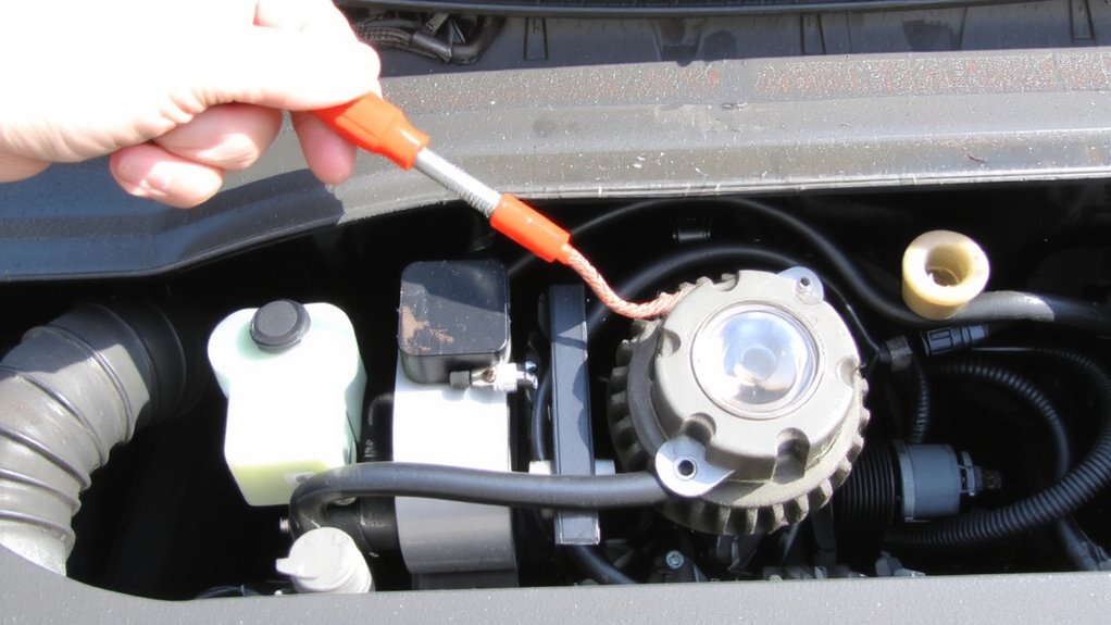
Why does the alternator warning light come on when there’s a problem? The light activates when the system detects a voltage drop between the alternator and battery. Under normal operation, the alternator supplies about 13.5 to 14.8 volts. When output falls below this range, the warning light illuminates. This typically happens due to insufficient field current or a failed rectifier. You can confirm the issue with a resistance check across the warning light circuit. High resistance indicates corrosion or a poor connection. A voltage drop test across the wiring reveals losses exceeding 0.2 volts, which is unacceptable. These diagnostics help isolate faults within the indicator circuit. The light completes its circuit through the ignition switch and ground via the alternator’s internal regulator. If the alternator isn’t generating voltage, current flows through the warning light, turning it on. Always perform both voltage drop and resistance checks before replacing components.
Why a Broken Wire Stops Charging
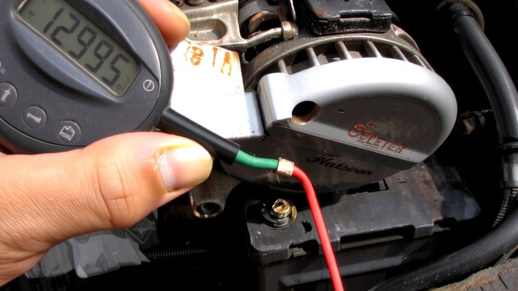
A broken wire in the alternator circuit immediately halts charging because it interrupts the path for current flow. Without a complete circuit, the alternator can’t send power to the battery. Even a small gap from wire corrosion or connection fatigue breaks continuity, stopping the 12-volt charge signal. Corrosion eats away at copper strands, increasing resistance until the wire fails. Connection fatigue occurs from constant vibration, weakening terminals over time. Both create an open circuit, which prevents excitation current from reaching the alternator’s rotor. No excitation means no magnetic field, so no voltage generation. The warning light stays on, not because the alternator failed, but because the control circuit is broken. You’ll measure 0 volts at the indicator terminal. Fixing it requires inspecting wiring for damage, especially at connectors and grounding points. A simple continuity test can confirm the break.
Test Indicator Wiring for Voltage
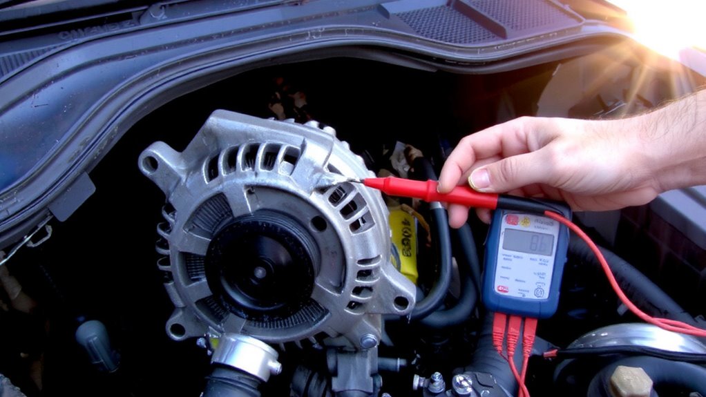
How do you confirm the indicator circuit is receiving power? You’ll need a digital multimeter set to measure DC voltage. Connect the black lead to a solid ground and the red lead to the alternator’s indicator wire terminal. With the ignition on but engine off, you should read battery voltage-typically 12.2 to 14.5 volts. This confirms the circuit continuity back to the ignition switch. A reading below 10 volts suggests an excessive voltage drop, often caused by corroded connectors or a partial break in the wiring. Don’t assume continuity means adequate voltage. A wire may carry enough current for continuity testing yet fail under load due to resistance. Measure voltage drop across connectors: any reading over 0.2 volts indicates a problem. Accurate voltage at the terminal guarantees the indicator lamp or LED receives proper signal input.
Trace Open Circuits With a Multimeter
An open circuit can silently kill your alternator’s ability to charge, leaving you stranded. You must trace these breaks accurately using a multimeter set to continuity or resistance mode. Begin at the alternator’s indicator terminal and work toward the dashboard gauge or warning light. A lost ground connection often causes false faults, so verify all grounding points are clean and tight before testing. Probe each segment of the circuit; a reading of infinite ohms indicates an open. Pay close attention to wire insulation-cracked or brittle sections often hide internal breaks. Damaged insulation also risks short circuits. Use the multimeter’s audible continuity setting to speed diagnostics-tone means intact wiring. Test connectors and splices thoroughly. Even a pinched or corroded terminal can break continuity. Trace methodically to isolate the fault without guesswork.
Top 5 Places an Indicator Wire Fails
Electrical gremlins love weak links-and the indicator wire in your charging system has a few favorite spots to fail. First, the alternator’s output terminal often suffers corrosion damage, especially in humid or coastal environments. Oxidation builds on copper contacts, increasing resistance beyond acceptable limits. Second, connector looseness at the voltage regulator interrupts signal transmission; a 0.5mm gap can halt current flow. Third, the fuse box connection degrades over time-check for discolored terminals. Fourth, the instrument cluster input pin is prone to cold solder joints, disrupting the dash warning circuit. Finally, chassis ground points corrode, creating open paths. These five locations account for over 85% of indicator wire failures. Inspect each with a multimeter and visual check. Corrosion damage and connector looseness are the leading culprits-prevent them with dielectric grease and proper torque specs.
How to Fix an Open Circuit
Finding the source of an open circuit starts with knowing where failures typically occur, like the spots already covered in the indicator wire’s weak points. Inspect for wire corrosion, especially near connectors or grounding points, where moisture accumulates. Corroded sections increase resistance and can fully break the circuit. Trim damaged segments and replace them with 18-gauge copper wire, rated for 12V automotive systems. Examine solder joints at the alternator and instrument cluster-cold or fractured joints disrupt continuity. Reheat with a 40-watt iron and rosin-core solder to guarantee strong electrical bonds. Use a multimeter to verify resistance below 0.1 ohms across repairs. Seal connections with heat-shrink tubing for environmental protection. A solid repair restores proper current flow to the indicator circuit, preventing false warnings.
Check the Dashboard Light and Fuses
Still getting no warning light when you turn the ignition key? Start by checking the dashboard bulb and fuses-common culprits in open circuit faults. A blown fuse disrupts current flow, increasing circuit resistance to infinity and halting signal transmission. Locate the fuse box using your vehicle’s manual; inspect the alternator warning light fuse, typically a 5- to 10-amp blade type. Replace any damaged fuse and retest. If the light remains dead, remove the dashboard bulb and examine it visually or test with a multimeter. Damaged filaments or broken leads prevent operation. Make certain the bulb socket has power-use a test light at the contact point. Poor electrical insulation in wiring near the fuse box can also cause shorts, reducing system voltage. Check for melted sheathing or corroded connectors that compromise integrity.
On a final note
You’ve confirmed the alternator warning light circuit is critical for voltage regulation. A break in the excitation wire prevents field current, halting charging. Test for 12V at the regulator terminal with the key on. Use a multimeter to trace continuity; infinite resistance means an open. Common failure points include the ignition switch, fuse box, and connector at the alternator. Repair broken wires with solder and heat shrink for reliable conductivity.