How to Bench Test an Automotive Alternator After Removal
Connect your alternator to a 12V battery using 40A-rated jumper wires, linking positive to B+ and negative to the casing. Power the field terminal (F or IL) with a fused 12V supply to start excitation. At 1,000 RPM, voltage should be 13.5–14.5V; at 2,500 RPM, it should rise to 13.8–14.8V. Check for over 50 mV AC ripple at B+ with a multimeter-excess indicates diode failure. Unusual noise, overheating, or voltage drops point to internal faults. Proper output confirms functioning windings and regulation. Inconsistent results suggest brush, regulator, or rectifier issues. A stable, ripple-free signal under load means the alternator is likely good. Further inspection could reveal hidden wear or intermittent faults.
Notable Insights
- Use a 12V battery and heavy-gauge jumper wires to power the alternator’s B+ and field (F) terminals during bench testing.
- Connect the multimeter to the B+ and ground to measure output voltage at 1,000 and 2,500 RPM.
- Expect 13.5–14.5V at idle and 13.8–14.8V at higher RPM; steady readings indicate proper regulation.
- Test for AC ripple with the multimeter on AC scale; over 100 mV suggests faulty diodes or rectifier.
- Inspect for bearing noise, overheating, or voltage fluctuations, which indicate internal damage requiring rebuild or replacement.
Gather Tools to Bench Test an Alternator
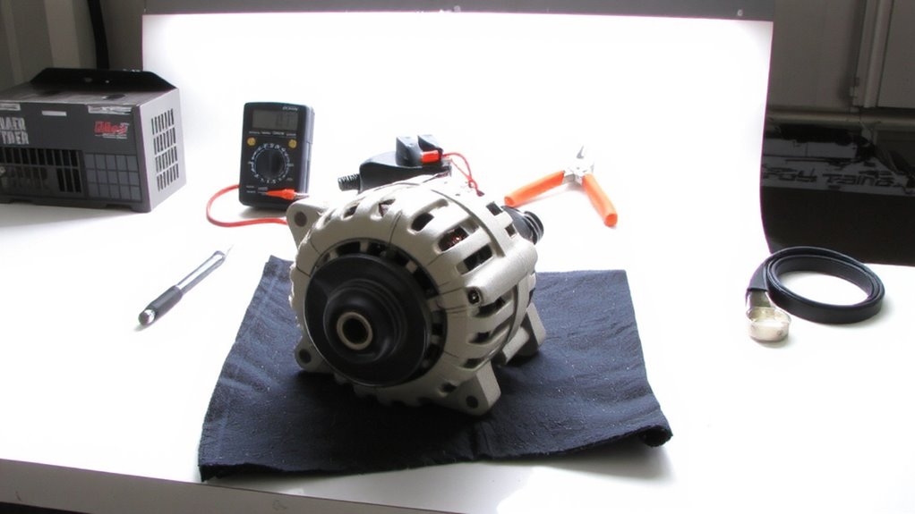
You’ll need a few essential tools to properly bench test an alternator, and having the right equipment guarantees accurate results. Begin with a digital multimeter capable of measuring DC voltage to 20 volts and amperage up to 30 amps. You’ll also need heavy-gauge jumper wires with insulated alligator clips rated for 40 amps. A 12-volt battery in good condition acts as a stable power reservoir. For accurate load testing, use a variable resistive load bank or a calibrated carbon pile tester. Always prioritize safety precautions: wear safety glasses, remove metal jewelry, and work in a dry, well-ventilated area. Your test environment setup should include a non-conductive workbench surface and grounding straps. Guarantee tools are rated for automotive electrical systems to prevent misdiagnosis. Consider using a high-quality best alternator brands unit when replacement is necessary to ensure long-term reliability and performance.
Connect the Alternator to a Power Source
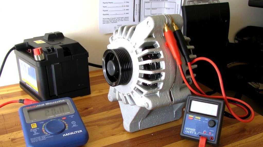
Once the test setup is confirmed secure, connect the alternator to a 12-volt power source using heavy-gauge jumper wires rated for at least 40 amps to handle high current loads without overheating. Attach the positive lead to the alternator’s battery terminal (B+) and the negative to the casing, ensuring solid ground. You must supply field excitation to the alternator’s control circuit-typically terminal F or IL-to activate the rotor’s magnetic field. Use a fused 12-volt feed to the field terminal to prevent damage. Proper brush contact is essential; worn or stuck brushes interrupt field excitation, causing failure. Inspect for smooth sliding movement and visible wear. Jostle the brushes gently to confirm contact continuity. Without consistent brush contact, voltage generation won’t initiate. The alternator relies on this small current to begin power production-like a spark plug igniting fuel. Double-check all connections before proceeding.
Test Alternator Voltage Output at Idle and High RPM
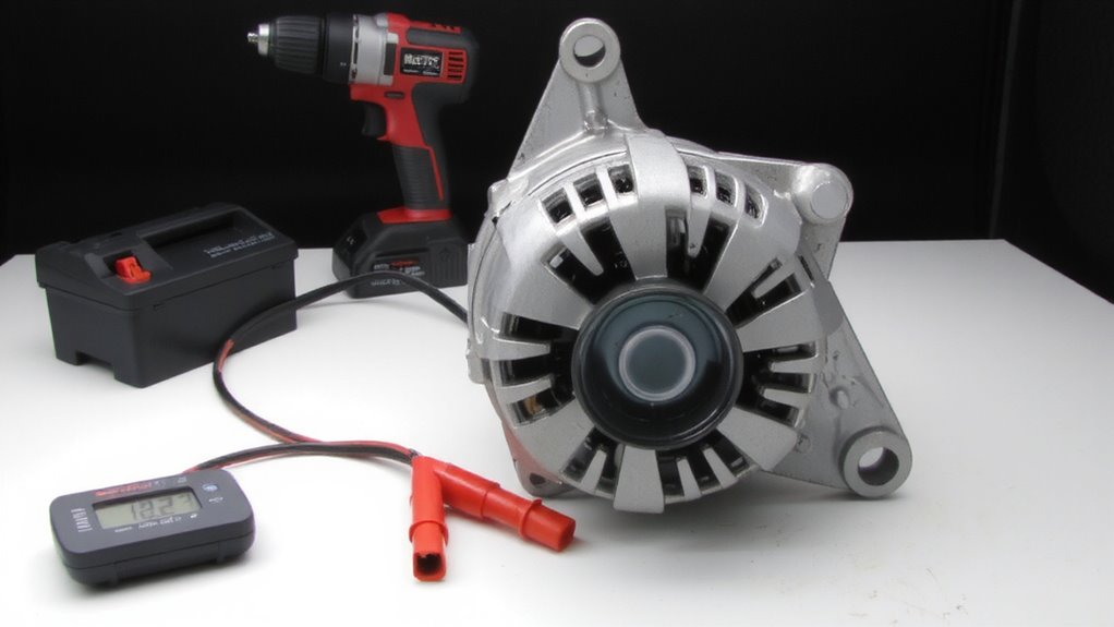
How does an alternator respond under varying engine speeds? You’ll test voltage output at idle and high RPM to verify performance. At idle (around 1,000 RPM), a healthy alternator produces 13.5–14.5 volts. When you increase to 2,500 RPM, voltage should remain stable-not exceeding 15 volts. Fluctuations suggest issues with voltage regulation or alternator phase balance. Use a multimeter across the battery terminals while running the test. A reliable car multimeter is essential for accurate voltage readings during this diagnostic procedure.
| RPM Level | Expected Voltage |
|---|---|
| Idle (1,000) | 13.5–14.5V |
| High (2,500) | 13.8–14.8V |
Consistent output confirms proper field coil resistance and diode trio function. Poor phase balance causes ripple and reduces efficiency. Always maintain steady RPM during testing. Abrupt voltage spikes or drops indicate internal faults. This test guarantees the alternator sustains electrical loads under real-world conditions.
Diagnose Diode Failure With AC Ripple Check
A stable DC output doesn’t tell the whole story-hidden within that voltage can be AC ripple caused by faulty diodes. Use your digital multimeter’s AC voltage setting to check for ripple. Connect the leads to the alternator’s output (B+) and ground while running at 2000 RPM. Over 50 mV AC suggests trouble. Excessive ripple indicates diode leakage or rectifier failure, where damaged diodes fail to block reverse current efficiently. A fully functioning rectifier converts AC to smooth DC; compromised diodes allow AC fluctuations to pass through. This ripple stresses the electrical system and can mimic battery issues. Severe diode leakage often results in voltage drops under load and reduced charging efficiency. If ripple exceeds 100 mV AC, diode replacement or a new rectifier bridge is necessary. Always confirm these readings with the alternator unloaded and battery disconnected to avoid false signals.
Spot Common Alternator Failures (No Charge, Noise, Overheating)
Silence from your ammeter or a dimming dashboard isn’t just annoying-it’s a red flag. You’re likely facing a no-charge condition caused by internal alternator faults. Bearing wear is a common culprit; when bearings degrade, the rotor wobbles, causing belt misalignment and eventual failure to spin freely. You might notice a high-pitched whine or grinding noise during operation-audible signs of mechanical breakdown. Overheating often follows, triggered by excessive friction or electrical overload. Poor voltage regulation leads to undercharging or overcharging, both damaging to your battery and electronics. A healthy alternator maintains output between 13.8 and 14.7 volts under load. Voltage spikes or drops outside this range indicate failed regulators or worn brushes. These symptoms-noise, heat, and erratic output-point to specific internal failures. Inspect thoroughly. You can confirm bearing condition by manually rotating the pulley; resistance or roughness means replacement is needed.
Interpret Results: Is Your Alternator Good or Bad?
You’ve inspected for bearing wear, checked for unusual noise, and verified voltage output under load-now it’s time to make a final determination. A healthy alternator outputs 13.8 to 14.4 volts under load. If your reading falls outside this range, there’s likely an issue. Voltage fluctuation exceeding ±0.5 volts indicates a failing regulator or damaged diodes. Stable voltage is critical-think of it like a steady heartbeat for your electrical system. Check the ground connection thoroughly; poor grounding causes misleading readings and erratic performance. Confirm the alternator case is clean and makes direct contact with the test bench ground. If voltage remains low or fluctuates despite a solid ground connection, the alternator is faulty. Persistent irregularities, especially under load, confirm internal failure. Record all measurements. Consistent numbers within spec mean the alternator is good. Inconsistent or out-of-range results mean it’s bad.
Can You Fix It or Should You Replace It?
What’s the smarter move when your alternator fails the bench test-rebuild it or replace it outright? You should weigh cost, time, and reliability. If voltage regulation is off, the internal circuitry or voltage regulator is likely faulty. Failed voltage regulation means your battery won’t charge properly-either overcharging or undercharging. Internal resistance, when too high, generates excess heat and reduces output efficiency. Test diodes and stator windings; if they’re defective, repair parts are often cheaper than a new unit. However, remanufactured alternators come tested, with guaranteed voltage regulation and low internal resistance. Rebuilding requires skill and tools, and long-term reliability isn’t always assured. For most drivers, replacement is faster and more dependable. Modern alternators are complex, and mismatched components can lead to premature failure. Unless you’re experienced, replacing it guarantees proper performance and avoids repeated bench testing.
On a final note
You now know how to properly bench test an alternator. Connect it to a 12V power source to excite the field circuit. Use a multimeter to check voltage at the output terminal. A healthy alternator produces 13.8–14.8 volts at 2,000 RPM. Excessive AC ripple (over 50 mV) indicates diode failure. Unusual noise or overheating suggests internal wear. If voltage falls outside specs or ripple is high, the unit is faulty. Replacement is usually more reliable than repair.