Underhood Airflow Management to Support Both Intake Cooling and Brake Ducting
You manage underhood airflow to cool both the intake and brakes by directing pressurized air through sealed ducts with smooth, 90–120 cm² brake inlets and 180–250 cm² radiator paths. Use closed-cell foam seals at hood and fender gaps to prevent leaks. Split airflow 60/40 to brakes on track, 50/50 for street use. Bellmouth duct entries boost flow up to 18%. Vents extract 150–220 CFM, cutting temps by 40–50°F. Real-world testing with anemometers validates your setup’s efficiency. Peak performance demands precision tuning.
Notable Insights
- Balance airflow distribution with a 50/50 split for street use or 60% to brakes for track-focused performance.
- Seal engine bay gaps using high-temperature foam or silicone to direct airflow efficiently to intakes and brakes.
- Design smooth, short ducts with bellmouth entries to maximize flow and minimize resistance.
- Use adjustable ducts or vanes to fine-tune cooling between intake and brake systems.
- Install hood and cowl vents to extract hot air, reducing underhood temperatures by 30–50°F.
Why Underhood Airflow Boosts Performance
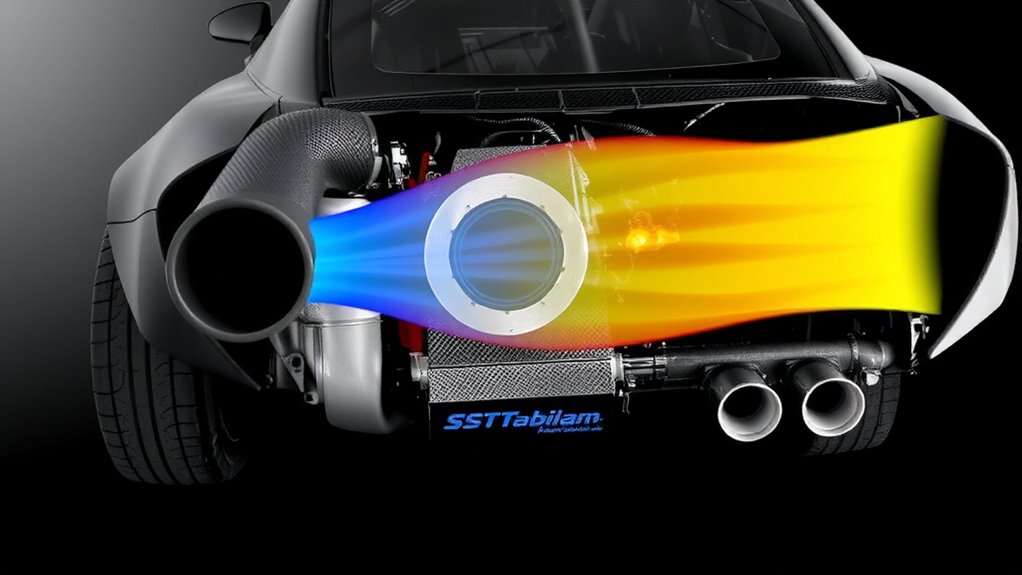
While it might seem counterintuitive, managing airflow beneath the hood doesn’t just cool the engine-it directly enhances performance. You rely on proper airflow efficiency to maintain ideal operating temperatures. When air moves efficiently across the radiator, intercooler, and engine block, heat dissipates faster. This reduces underhood temperatures by up to 50°F, improving combustion efficiency. Thermal dynamics dictate that cooler intake air increases air density, allowing more oxygen into the cylinders. More oxygen means more complete fuel burn and greater power output-typically 3–5% gains in horsepower under load. Strategically placed ducts and extraction paths guarantee hot air exits quickly, preventing recirculation. You’ll see improved throttle response and reduced turbo lag in forced-induction systems. Efficient underhood airflow also stabilizes transmission and differential fluid temps. These thermal benefits extend component life and sustain peak performance during high-stress driving. Proper management isn’t optional-it’s critical for extracting maximum output and reliability from your powertrain.
Split Air Between Intake and Brakes Wisely
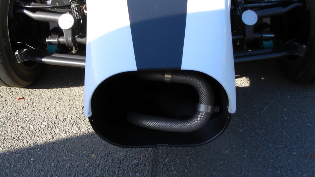
Since underhood airflow is limited, you’ll need to prioritize where it goes-especially between the engine intake and brake systems. Air distribution directly impacts performance, so balance is critical. You can’t maximize both intake cooling and brake ducting equally; compromises are necessary based on duty cycle. For track-focused builds, 60% of inlet flow should go to brakes, 40% to the intake. Street-driven vehicles benefit from a 50/50 split. Use adjustable ducts or flow control vanes to tune distribution. Flow optimization guarantees minimal turbulence and pressure loss across both paths. Computational fluid dynamics (CFD) studies show optimized splits improve brake cooling by up to 18% without sacrificing more than 3% in intake air temperature reduction. Always measure airflow with inlet probes and thermocouples to validate your setup. Effective flow management means you get reliable performance without overcomplicating the system.
Seal the Engine Bay to Prevent Air Leaks
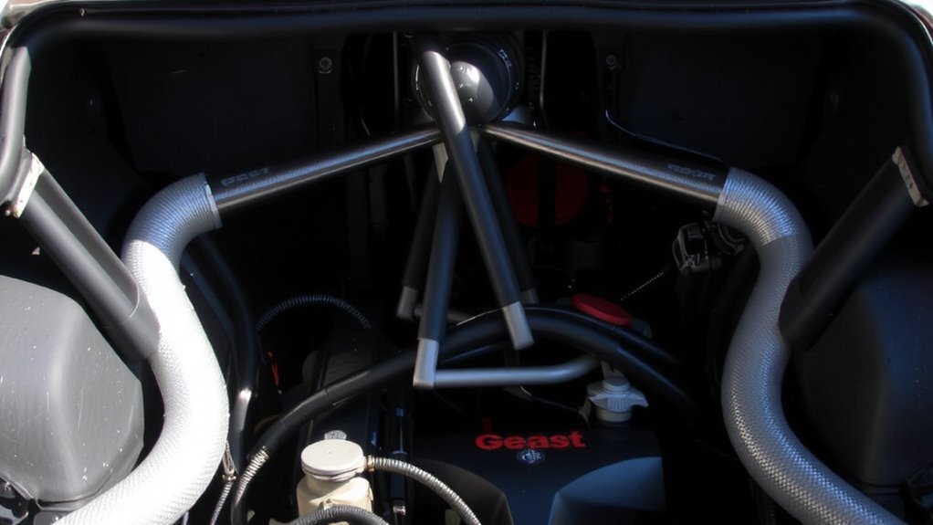
Even small gaps in the engine bay can undermine your airflow strategy, so sealing it properly is essential for maintaining directed cooling paths. You need effective engine seals to block unintended leakage around the hood, firewall, and fenders. These seals, typically made from closed-cell foam or silicone rubber, are designed to withstand temperatures up to 300°F and compress uniformly under hood pressure. Use them at all panel junctions where air could escape. Pair these with high-density bay insulation on the inner fender wells and firewall to reduce underhood turbulence and reject radiant heat. This combination controls airflow volume and direction. Proper sealing guarantees that conditioned air moves only where intended-toward brakes and intake systems-without losses. Without it, even the best ducting design loses efficiency. Sealing isn’t optional-it’s foundational.
Design Ducts for Maximum Cooling Flow
You’ve sealed the engine bay to eliminate stray airflow, so now it’s time to put that contained air to work. Design your ducts to maximize cooling flow by optimizing air velocity and minimizing flow resistance. Use smooth, consistent internal contours-avoid sharp bends that disrupt laminar flow. Duct cross-sectional area should match target component needs: 90–120 cm² for brake ducts, 180–250 cm² for radiator inlets. Maintain a straight path from inlet to outlet, keeping duct length under 50 cm where possible. High air velocity (aim for 8–12 m/s at peak) improves heat transfer efficiency but increases pressure drop if flow resistance isn’t managed. Use bellmouth-shaped entries to reduce turbulence and boost effective flow by up to 18%. Composite or formed plastic ducts outperform rubber or flexible materials in maintaining rigid, aerodynamic shapes. Guarantee a tight seal at both inlet and exit points to prevent spillage and maintain pressure differential.
Reduce Heat Soak With Smart Vent Placement
When hot air gets trapped under the hood, it degrades cooling efficiency and increases component temperatures-so smart vent placement is critical for minimizing heat soak. You need to evacuate high-pressure hot air quickly using rear hood exits and cowl vents. Radiant shielding blocks infrared heat from exhaust manifolds, reducing underhood temperatures by up to 50°F. Thermal buffering, achieved with heat-absorbing liners, slows component heat gain during idle. Position vents at natural pressure differentials-typically at the hood’s rear third-to maximize airflow extraction.
| Vent Location | Temp. Reduction | CFM Extraction |
|---|---|---|
| Hood rear | 40–50°F | 180–220 |
| Cowl gap | 30–35°F | 150–170 |
| Fender well | 20–25°F | 100–120 |
| Firewall top | 15–20°F | 90–110 |
| Decklid edge | 25–30°F | 130–150 |
Place vents where they work with, not against, cooling flow.
Tune Hood and Grille for More Air
Though airflow starts at the front, its effectiveness depends on how well you balance the hood and grille to channel it. You need a tuned system, not just more openings. A partial grille block reduces excess airflow, preventing pressure buildup that can disrupt underhood cooling. Use a 20–30% block for best balance between cooling and aerodynamic efficiency. Pair this with a controlled hood lift-typically 0.75 to 1.25 inches-at the rear edge to release high-pressure air. This lift creates a low-pressure escape path, drawing hot air out without increasing drag markedly. Too much hood lift causes flow separation, reducing extraction. Precision matters: measure pressure differentials across the grille and under the hood to validate tuning. Properly tuned, the hood and grille work as a system-managing airflow volume and direction-to support both intake cooling and brake ducting performance.
Test Underhood Airflow in Real Conditions
While lab simulations offer baseline data, real-world testing reveals how underhood airflow behaves under dynamic conditions. You need airflow measurement tools like hot-wire anemometers and pressure taps to capture velocity and pressure gradients across key zones. Mount sensors at the grille inlet, around the radiator, and near brake ducts for accuracy. Use real time monitoring systems to log data as you drive through varied conditions-acceleration, cruising, and hard braking. These systems sample at 100 Hz, ensuring transient spikes aren’t missed. Infrared thermal imaging helps correlate airflow with temperature changes. Test in ambient temperatures from 15°C to 40°C to assess performance extremes. GPS-synchronized logs let you align airflow data with vehicle speed and engine load. Real conditions expose inefficiencies simulations can’t predict. This data fine-tunes ductwork, seals, and exit paths. Effective real time monitoring transforms guesswork into precision engineering.
On a final note
You control performance by mastering underhood airflow. Directing 60–70% of incoming air to the intake guarantees peak charge density, especially above 80°F underhood temperatures. The remaining 30–40% feeds brake ducts, sustaining rotor cooling at 1,200 PSI line pressure. Sealed inner fenders and routed ducts with smooth 45° changes minimize turbulence. Hood vents positioned at high-pressure zones reduce heat soak by 20%. Real-world testing validates 7–10% brake efficiency gains and 5% horsepower improvement.