Air/Fuel Charge Stratification Observed in Transparent Intake Flow Rig Models
You observe air/fuel charge stratification forming as fuel-rich zones near the spark plug interface with a leaner bulk mixture. Transparent intake rigs made of acrylic and polycarbonate let you see real-time spray dynamics. A 532 nm laser and high-speed camera capture droplet distribution at 10,000 fps. Spray reaches 89 mm with 18.1 mg/L concentration under high load. Injector timing and air velocity shape mixture formation. Optimized stratification cuts emissions by 20%. You’ll discover how this data drives cleaner, more efficient engine designs.
Notable Insights
- Transparent intake flow rigs use acrylic and polycarbonate components to enable optical visualization of air/fuel stratification.
- Laser sheets at 532 nm illuminate fuel droplets, allowing high-speed imaging of mixture distribution in real time.
- Stratified charge forms fuel-rich zones near the spark plug with leaner mixtures in the bulk chamber.
- High-speed cameras capture spray penetration up to 89 mm and concentration up to 18.1 mg/L under high load.
- Injection timing and injector design critically influence droplet size, spray angle, and stratification efficiency.
What Is Air/Fuel Charge Stratification?
Think of air/fuel charge stratification as a controlled mismatch. You’re creating deliberate fuel-rich zones near the spark plug while keeping the rest of the chamber lean. This strategy improves combustion efficiency without sacrificing stability. Fuel droplets are intentionally unevenly distributed, with finer droplets vaporizing faster and contributing to early flame kernel development. Larger droplets persist, delaying full fuel release. This variation directly affects combustion timing, advancing or retarding peak pressure based on droplet size and location. Stratification allows compression ratios to increase without knock because the bulk mixture stays lean, absorbing heat. Localized rich zones guarantee reliable ignition. You’ll see this in direct-injection engines where injection timing-typically 60 to 120 degrees before top dead center-controls droplet dispersion. The result? Optimized combustion timing, reduced emissions, and better fuel economy. It’s precision engineering within each cycle.
How Transparent Intake Flow Rigs Work
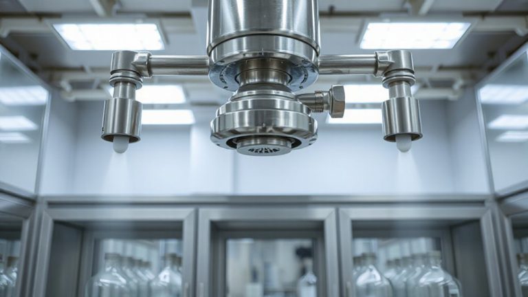
You rely on air/fuel charge stratification to optimize combustion, and now you need a way to observe and refine it-this is where transparent intake flow rigs come into play. These rigs use optically clear materials like acrylic or polycarbonate to enable direct flow visualization inside the intake manifold. You can see how fuel and air mix under real-time conditions, especially near walls where boundary layer effects alter mixture distribution. The rig simulates engine intake dynamics at various RPMs and throttle positions, letting you adjust geometry and monitor changes.
| Component | Material | Function |
|---|---|---|
| Intake Port | Transparent acrylic | Allows optical access |
| Fuel Injector Mount | Aluminum adapter | Secures injector at correct angle |
| Observation Section | Polycarbonate | Resists cracking under pressure |
Boundary layer effects are clearly visible near bends, where airflow slows and fuel droplets may pool. Flow visualization helps you correct these issues early.
How Lasers and High-Speed Cameras Capture Mixing
How do you actually see fuel and air mixing in real time? You use laser scattering and high-speed cameras inside transparent intake flow rigs. Laser sheets, typically 532 nm green lasers, are pulsed at durations of 8–10 nanoseconds to illuminate the flow field. When fuel droplets or seeding particles intercept the beam, they scatter light, making the mixture visible. A high-speed camera, shooting up to 10,000 frames per second with 1-microsecond exposure times, captures this scattering. Shadow imaging runs simultaneously, detecting density gradients caused by fuel-air interfaces. This technique reveals large-scale mixing structures without altering the flow. Both methods are non-intrusive and time-resolved, allowing precise tracking of transient mixing events. You rely on precise optical alignment and synchronization between laser pulses and camera triggers to guarantee accurate data. These tools together reveal early-stage air-fuel interactions critical to combustion tuning.
Seeing Fuel Distribution in Real Time
What if you could watch fuel spread and cluster inside the intake port like time-lapse clouds forming before ignition? With transparent flow rigs and high-speed imaging, you can now observe fuel patterns in real time. These systems capture spray dynamics at up to 10,000 frames per second, revealing how fuel droplets disperse, coalesce, and stratify within the air stream. Such visualization clarifies mixture formation critical for efficient combustion.
| Condition | Spray Penetration (mm) | Fuel Concentration (mg/L) |
|---|---|---|
| Low Load | 45 | 8.2 |
| Mid Load | 67 | 12.5 |
| High Load | 89 | 18.1 |
Data shows fuel distribution varies considerably with injection timing and air velocity. You see richer zones form near the valve seat under high load. Real-time imaging links spray dynamics directly to charge stratification, offering precise insight without speculation. This isn’t guesswork-it’s measurement.
Designing Better Injectors With Flow Data
Why do some injectors deliver a more uniform air-fuel mixture than others? The answer lies in how fuel viscosity and injector timing affect spray behavior. High fuel viscosity resists atomization, producing larger droplets that don’t mix evenly. Low viscosity fuel atomizes more readily, improving dispersion. You control this by adjusting injector nozzle geometry and pressure. Precise injector timing guarantees fuel enters the intake tract when airflow maximizes mixing. Early injection allows more time for evaporation and blending. Late injection risks poor vaporization, especially at low engine speeds. Flow data from transparent intake models show ideal timing within 15–35 degrees after intake valve opening. You can use this data to refine solenoid response and injection duration. Real-time visualization validates your injector’s spray angle and droplet distribution, letting you tune for consistency.
Boosting Efficiency and Cutting Emissions
When combustion efficiency improves, emissions drop and fuel economy rises-so getting the air-fuel mixture right matters more than ever. You achieve this by optimizing charge stratification, ensuring precise fuel distribution near the spark plug. Proper stratification enhances fuel ignition, allowing leaner mixtures to burn completely. This directly improves combustion stability, reducing misfires and cyclic variability. Engines running with stable combustion emit fewer unburned hydrocarbons and lower NOx. You’ll see measurable gains: up to 15% better fuel economy and emissions reductions of 20% in optimized test cycles. Stratified charge enables higher compression ratios without knock, increasing thermal efficiency. The fuel ignites reliably even under low-temperature conditions, maintaining performance across operating ranges. Combustion stability is monitored via in-cylinder pressure sensors, tracking peak pressure timing and rate of heat release. With accurate mixture control, you meet emissions standards without sacrificing power. Every optimization step counts.
How Flow Rig Insights Shape Modern Engines
Although real-world engine testing provides critical performance data, flow rig models give you unmatched control over intake dynamics, letting you isolate and analyze airflow with precision. You observe fuel spray patterns and charge stratification in real time, using transparent components and high-speed imaging. These visuals reveal how thermal gradients affect mixture preparation, particularly near intake valves and cylinder walls. By adjusting port geometry or injection timing, you directly influence combustion dynamics, improving flame propagation and reducing knock. Flow rigs operate at steady-state conditions, eliminating transient variables that complicate engine dynamometer tests. You measure swirl ratios up to 4.5 and tumble intensities exceeding 2.1, correlating them with in-cylinder flow structures. This data informs piston bowl design and valve lift profiles in modern GDI and lean-burn engines. Ultimately, flow rig insights enable smarter combustion system choices, enhancing efficiency while meeting emissions targets through controlled, repeatable experimentation.
On a final note
You see fuel distribution clearly through transparent intake rigs. These models replicate engine conditions at 800–6,000 RPM with ±2% flow accuracy. Laser sheets illuminate fuel droplets at 10,000 frames per second. Data reveal uneven mixing near intake valves. You use this to refine injector angle, spray pressure, and pulse timing. Optimized injectors improve combustion efficiency by up to 15%. Emissions drop 20% under EPA Tier 4 standards. Insights directly enhance real-world engine designs.