Avoiding Boundary Layer Separation in Large-Diameter Intake Tubing Runs
Keep your intake air moving fast enough to stay attached. Large-diameter tubes slow airflow, letting the boundary layer separate under adverse pressure gradients. Use tubing sized to maintain velocity-below 70 CFM, avoid 4-inch diameter. Install bends with a minimum 1.5× diameter radius; for 4-inch tube, that’s 6 inches. Mandrel-bend all curves. Smooth walls below 32 Ra reduce drag. Add vane-style straighteners 6 diameters past disturbances. Test flow uniformity within ±5%. Solutions compound-optimize each section to see real gains.
Notable Insights
- Maintain adequate air velocity by properly sizing large-diameter intake tubing to prevent boundary layer stagnation.
- Use gradual bends with a minimum centerline radius of 1.5× tube diameter to avoid flow separation.
- Ensure smooth interior surfaces with roughness below 32 microinches Ra to reduce friction and maintain attached flow.
- Install mandrel-bent tubing to preserve consistent internal geometry and minimize turbulence in bends.
- Place flow straighteners at least 6 tube diameters downstream of disturbances to reduce swirl and stabilize airflow.
What Is Boundary Layer Separation?
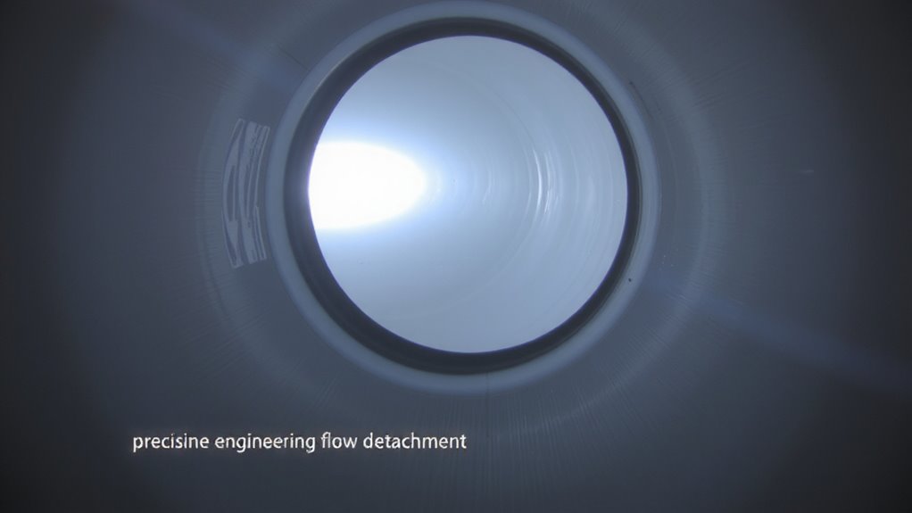
When airflow moves across the inner surface of intake tubing, it doesn’t travel at a uniform speed from the center to the wall. Instead, friction slows air near the wall, creating a thin layer called the boundary layer. You’re seeing flow dynamics in action-air in this layer has reduced momentum. If pressure gradients shift unfavorably-rising pressure along the flow direction-the sluggish air can’t push forward. It stalls, then reverses. That’s boundary layer separation. It disrupts smooth airflow, reduces engine efficiency, and increases turbulence. Separation doesn’t happen instantly; it begins when the adverse pressure gradient overcomes the kinetic energy within the boundary layer. Think of it like a car trying to climb a steep hill with too little speed-it rolls backward. In intake systems, this means lost performance. Managing flow dynamics and minimizing adverse pressure gradients are essential. You’ll want smooth internal finishes and gradual changes to keep airflow attached and maintain maximum volumetric efficiency.
Why Large-Diameter Intake Tubes Cause Flow Separation
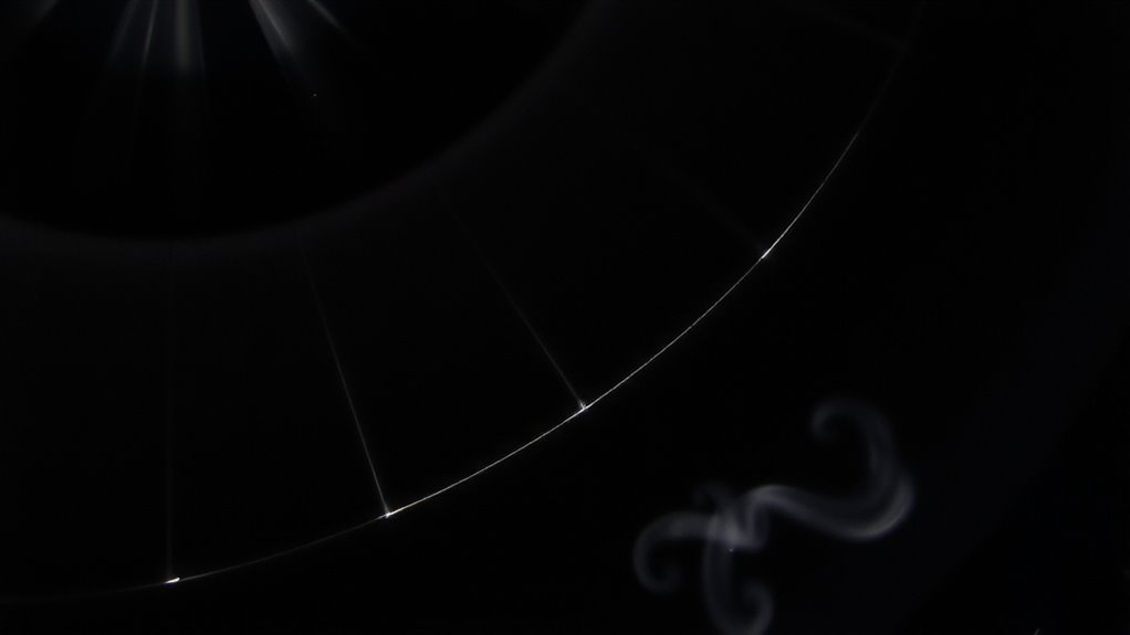
Though larger tubing might seem like an easy way to boost airflow, going too big can actually hurt performance by triggering boundary layer separation. You reduce air velocity when you oversize intake tubing, weakening the boundary layer’s attachment to the wall. Lower velocity means the airflow can’t overcome adverse pressure gradients, especially near the tube walls. These adverse pressure gradients push slow-moving air backward, detaching the boundary layer from the surface. Once separation starts, turbulent eddies form and grow, disrupting smooth airflow. These eddies increase drag and reduce effective flow area, cutting engine efficiency. In a 4-inch tube running at 70 CFM, velocity drops below 20 ft/s-too low to maintain attached flow. Think of it like a car losing traction on ice: the energy is there, but it can’t grip. Properly sized tubing maintains velocity and minimizes separation risk, keeping airflow stable and efficient.
Use Gradual Bends to Prevent Airflow Stall
A sudden bend in your intake tubing can trigger airflow stall just as easily as an oversized tube causes separation. Sharp corners disrupt smooth airflow, forcing the boundary layer to detach from the wall. This creates turbulence and reduces volumetric efficiency. To prevent this, use bends with a minimum centerline radius of 1.5 times the tube diameter. For a 4-inch tube, that means a 6-inch radius bend. Gradual bends maintain attached flow, keeping velocity uniform across the cross-section. Abrupt changes cause pressure imbalances, increasing flow separation risk. High-performance applications require bends of 2:1 or greater radius-to-diameter ratios. Mandrel-bent tubing guarantees consistent internal geometry, avoiding kinks. Unlike crush bends, mandrel-formed curves eliminate internal deformations. This preserves laminar characteristics through the turn. Proper bend design reduces flow loss by up to 35% compared to sharp corners. Always prioritize smooth curvature over compact routing. Air behaves like traffic-it slows and stalls at sharp turns but flows freely with gradual arcs.
Smooth Interior Walls to Maintain Laminar Flow
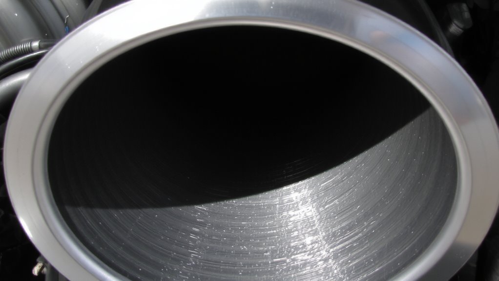
Your intake system’s efficiency hinges on the smoothness of the tubing’s inner surface. Even slight wall roughness disrupts airflow, triggering early boundary layer separation. A high-quality surface finish-ideally under 32 microinches Ra-ensures minimal friction drag and sustains laminar flow. Rough surfaces create localized turbulence, increasing pressure drop and reducing volumetric efficiency. Smooth-walled aluminum or polished stainless steel tubing maintains consistent airflow velocity profiles. For example, at 100 CFM, a smooth tube can reduce pressure loss by up to 28% compared to a textured interior. Wall roughness above 64 microinches markedly degrades performance, especially in large-diameter runs over 4 inches. Think of it like sliding on ice versus gravel-the smoother the path, the less energy you lose. Always specify tubing with certified surface finish ratings. Proper finishing techniques like honing or electropolishing make a measurable difference in airflow stability and engine performance.
Install Vane-Based Flow Straighteners to Reduce Swirl
Swirl in the intake airflow-often caused by sharp bends, uneven plenum entries, or turbocharger discharge-disrupts the smooth velocity profile needed for efficient combustion. You can counteract this using vane-based flow straighteners. These devices consist of aerodynamically shaped fins that guide airflow into a uniform direction. Proper vane alignment is critical; even 5° of misalignment increases turbulence by up to 18%. Install straighteners at least 6 tube diameters downstream of disturbances for best results. Each vane set typically reduces swirl by 60–85%, verified through swirl measurement using vane anemometers or computational fluid dynamics. Flow straighteners made from 304 stainless steel withstand temperatures up to 800°F and offer longevity in high-performance applications. Their low blockage ratio-under 12%-ensures minimal pressure drop. When correctly applied, they restore laminar flow and support consistent air-fuel mixing, increasing engine efficiency and reducing boundary layer separation risks.
Avoid Sudden Changes in Tube Diameter
While airflow behaves predictably in uniform ducts, it reacts poorly to abrupt changes in tube diameter, so you’ll want to eliminate sudden expansions or contractions in your intake system. Flow expansion causes air to decelerate rapidly, creating a strong adverse pressure gradient along the tube wall. This gradient forces the boundary layer to separate, increasing turbulence and robbing engine efficiency. You should use gradual changes-taper angles no greater than 7 degrees-to allow smooth recompression. A sudden 3-inch to 5-inch expansion increases drag by up to 40% compared to a 10-inch tapered section. Such sharp changes can induce separation zones extending over 12 inches downstream. Keep diameter changes minimal or use conical diffusers with included angles under 14 degrees. This maintains attached flow and minimizes losses. Remember, consistent cross-sections reduce pressure fluctuations. Avoiding abrupt changes preserves kinetic energy in the airstream, boosting volumetric efficiency and preventing unstable intake behavior.
Test Flow Stability Early and Often
Often, the best way to catch airflow issues is before they become problems-so test early and test often. You need consistent flow uniformity across the intake system to prevent boundary layer separation. Without it, airflow detaches, reducing efficiency and increasing turbulence. Check for irregular pressure gradients during initial setup and after each modification. Sudden changes in velocity or direction create adverse pressure gradients, which disrupt smooth airflow. Use pitot tubes or flow hoods to measure velocity profiles at multiple cross-sections. Maintain variation within ±5% of mean velocity for stable performance. Test under real operating conditions, not just at peak flow. Early detection of non-uniform flow lets you adjust bends, changes, or obstructions before losses compound. Frequent verification maintains peak pressure distribution and sustains efficient airflow. Remember, a small imbalance today can trigger major separation tomorrow.
On a final note
You prevent boundary layer separation by optimizing airflow dynamics. Use bends with radii at least 1.5× the tube diameter to reduce flow disruption. Smooth, low-roughness interiors-like polished aluminum or molded composite-minimize friction losses. Install vane-style straighteners at tight turns to eliminate swirl. Never allow sudden diameter changes; maintain gradual changes. Test with pitot tubes or smoke flow visualization early. Stable, high-velocity intake flow directly improves engine efficiency and power delivery.