Testing Ignition Control Circuit From ECU to Coil
You test the ignition control circuit by checking for a 5V or 12V square wave signal from the ECU at the coil’s control wire using an oscilloscope. Confirm power (12–14V) and ground (less than 0.2 ohms) at the coil. A missing signal suggests wiring faults, poor connections, or ECU issues. Measure coil resistances: 0.4–2 ohms primary, 6k–15k ohms secondary. Spark timing relies on precise PWM pulses between 2–5ms-analyze waveform consistency. There’s more to uncover about signal integrity under load.
Notable Insights
- Use an oscilloscope to verify the ECU sends a PWM or square wave signal to the ignition coil during cranking.
- Check for 12V power and solid ground at the coil before assessing the ECU trigger signal.
- Confirm coil control wire has switching activity matching engine RPM; absence suggests ECU or wiring fault.
- Inspect wiring and connectors for damage, corrosion, or opens between the ECU and ignition coil.
- Test coil primary and secondary resistance values to rule out coil failure before diagnosing ECU issues.
Understand the Ignition Control Circuit
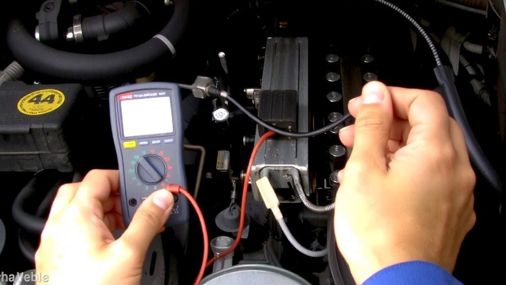
Think of the ignition control circuit as the brain behind your engine’s spark. It manages ignition timing and spark duration with precision. You rely on it to deliver the right spark at the exact moment. Ignition timing is controlled by the ECU, adjusting degrees before top dead center (BTDC) based on RPM and load. Typical timing ranges from 10° to 35° BTDC. Spark duration lasts about 1.0 to 1.8 milliseconds, depending on coil saturation. The module grounds the coil primary circuit, triggering the high-voltage spark. You’ll see voltages spike to 30,000–40,000 volts across the secondary winding. Fast switching guarantees clean combustion. This circuit uses feedback from crankshaft and camshaft sensors. It adapts timing dynamically, optimizing power and efficiency. You can’t ignore spark duration-too short, and combustion fails; too long, and the coil overheats. Reliable performance hinges on precise circuit operation.
Check for ECU-to-Coil Trigger Signals
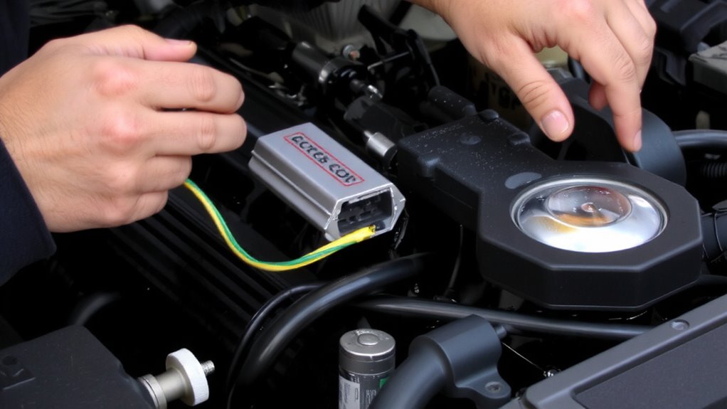
How do you know the ECU is actually telling the coil to fire? You need to verify the trigger signal sent from the ECU to the ignition coil. Using an oscilloscope, connect the probe to the control wire at the coil’s connector while grounding the reference. You should see a clean switching signal indicating coil activation and shutdown.
| Parameter | Expected Value | Tool Needed |
|---|---|---|
| Signal Type | PWM or square wave | Oscilloscope |
| Signal Frequency | Matches engine RPM | Scope with timebrown |
| Voltage Level | 5V or 12V logic | Digital multimeter |
| Duty Cycle | Varies with RPM | Oscilloscope |
| Coil Saturation | 2–5ms typical | Calculated from plot |
Signal frequency correlates directly with engine speed. Coil saturation time must be sufficient for full energy buildup but not so long that it causes delay. Look for consistent edges and no signal dropouts. High-quality ignition coils ensure reliable signal response and optimal spark performance.
Signal Present or Missing? What It Means?
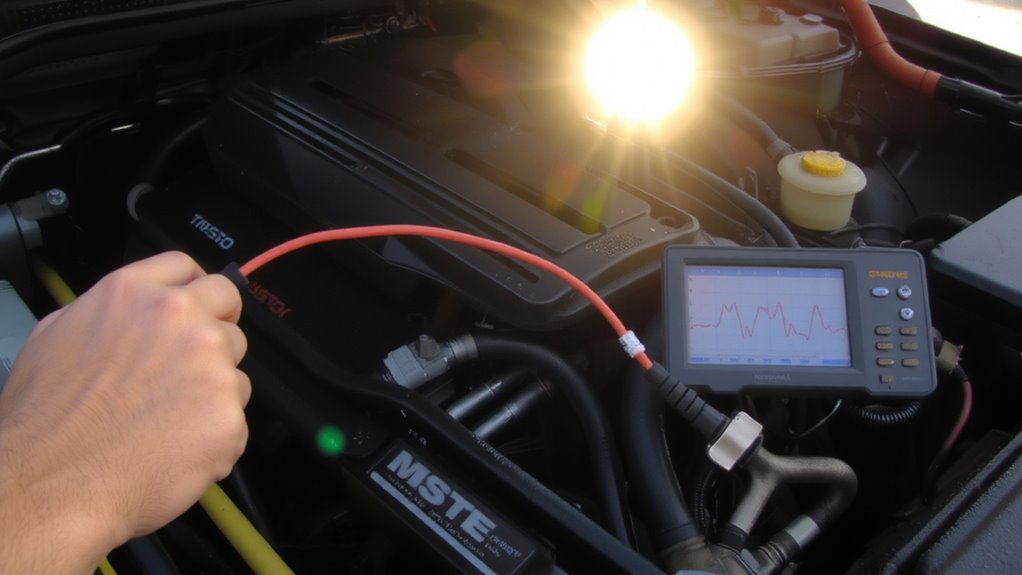
What happens when the scope shows no signal at all? You’ve confirmed power and ground, yet still see silence-this points to a missing trigger signal. A dead channel means either the ECU isn’t sending a pulse or the signal path is compromised. Start by checking ground integrity; a poor return path distorts or kills signals. Use a multimeter to verify less than 0.1 ohms resistance between the ECU ground and battery negative. Signal interference from nearby harnesses can also mask readings. Look for induced voltage where none should exist. Keep probe leads short and grounded properly during tests. Noise doesn’t typically erase an entire signal, so total absence suggests wiring breaks, open circuits, or connector corrosion-especially at the ECU harness. Don’t assume coil failure. Verify signal delivery first. Missing signal isn’t always ECU fault-intermittent wiring issues are more common than internal controller failure.
No Signal? Diagnose the ECU Output Issue
When the ignition control circuit shows no signal despite verified power and ground, the next step is confirming whether the ECU is actually generating an output. You must first guarantee the ECU receives stable power supply and solid ground integrity-without these, it can’t switch the ignition signal properly. Check the ECU’s power pins with a multimeter; you should see battery voltage (12–14V) with the key on. Verify ground integrity by testing resistance between the ECU ground and battery negative-readings should be less than 0.2 ohms. Use a lab scope on the ignition output wire to detect switching activity. No signal? The ECU may be faulty or inhibited by immobilizer systems, sensor faults, or internal circuit failure. Diagnostic trouble codes and ECU pinout specs help isolate the cause.
Inspect Wiring and Connections to the Coil
You can’t afford to overlook simple faults when diagnosing a dead ignition coil-start by visually inspecting the wiring and connector for damage, corrosion, or loose pins. Connector corrosion disrupts signal flow and can mimic ECU or coil failure. Pull the coil connector and examine terminals for greenish buildup or pitting. Clean with electrical contact cleaner if needed. Check wiring for fraying, cuts, or insulation melts near hot engine parts. Use a multimeter to verify continuity along the signal and power wires-any open or high-resistance circuits must be repaired. Test coil resistance at the primary and secondary windings; compare values to manufacturer specs, typically 0.4–2 ohms (primary) and 6k–15k ohms (secondary). Out-of-spec readings suggest internal failure, but rule out poor connections first-they’re far more common than coil defects.
On a final note
You now know the circuit’s basics and how to verify the ECU’s trigger signal. A missing signal indicates ECU or wiring faults. Use a digital multimeter to check for 5 V reference and grounding at the coil connector. Test for continuity in the control wire-resistance should be under 0.5 ohms per foot. Scope the signal: a clean square wave at 12 V confirms proper ECU output.