Developing a Fail-Safe Fueling Map for Turbocharged Engines With Leaky Injectors
You must account for parasitic fuel flow when building a fuel map on a turbocharged engine with leaky injectors. Unmetered fuel seepage causes rich idle and low-load conditions, forcing oxygen sensors to trim excessively. Test injectors at 40–60 psi; replace if leaking more than 2 cc/min. Adjust VE tables below 30 kPa MAP using leakage rates as static offsets. Fine-tune with 0.1 ms resolution and validate under real load-deviations above 90% load reveal timing errors. You’ll learn how to correct them next.
Notable Insights
- Diagnose injector leakage before tuning using pressurized drip tests to identify flows exceeding 1 drop or 2 cc/min.
- Adjust fuel tables by offsetting base pulse widths with measured leakage rates, especially at low load conditions.
- Treat leakage as a static fuel offset in VE tables calibrated below 30 kPa MAP for accurate idle and light-load AFR control.
- Use real-time AFR feedback and long-term trim behavior to detect residual fueling errors despite compensation.
- Validate corrected fuel maps under real and dyno load conditions, focusing on AFR accuracy from 50% to 90% engine load.
How Leaky Injectors Wreck Your Turbo Fuel Map
Even if your turbocharged engine starts smoothly, undetected fuel injector leaks can silently distort your fuel map and lead to chronic performance issues. You’re likely dealing with injector dribble, where fuel seeps past closed injectors, skewing air-fuel ratios during idle and low-load conditions. This unmeasured fuel disrupts stoichiometric balance, causing rich mixtures that confuse oxygen sensors and ECU feedback loops. Over time, your fuel map adapts incorrectly, embedding errors into long-term trims. A persistent fuel pressure drop between rail and injectors exacerbates the issue, often pointing to weak pumps or leaking check valves. These conditions mask as tuning problems, but they originate from hardware faults. Without correcting leaks first, any fuel map adjustments are temporary. The ECU can’t compensate for physical flow inconsistencies, especially under boost. Left unchecked, dribble increases carbon buildup, harms catalytic efficiency, and risks detonation during high-load operation. Regular maintenance with a high-quality fuel injector cleaner can help prevent deposit buildup and maintain optimal injector performance.
Detect Leaky Injectors Before Tuning
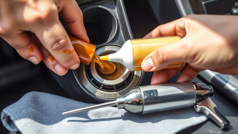
A fuel injector leak can undermine even the most carefully calibrated turbo fuel map, so you need to test for leakage before any tuning begins. Early diagnosis prevents running rich conditions that compromise engine safety and fueling accuracy. Perform baseline testing with the injectors removed and pressurized to rail pressure-typically 40–60 psi for port injection systems. Observe drip rate over 1 minute; any more than 1 drop indicates a leaking O-ring or failed pintle. Use a graduated cylinder to measure leakage in cc/min; exceeding 2 cc/min per injector requires replacement. Test both static leak-down and dynamic spray patterns using a test bench. A consistent, conical spray pattern guarantees proper atomization. Irregular streams or dripping suggest internal wear. Conduct these checks cold and hot to expose temperature-dependent faults. Baseline testing establishes system health and guarantees tuning starts from a known, reliable condition. For extended testing sessions away from power sources, consider using a portable power source such as a car camping fan power bank to maintain consistent electrical supply during diagnostics.
Tune Fuel Tables Around Injector Leakage
Some degree of injector leakage is inevitable over time, but you can’t ignore it when tuning fuel tables-especially on a turbocharged engine where precise air-fuel ratios are critical. You must account for the extra fuel leaking past the needles during closed periods. This parasitic flow distorts your base pulse width calculations, leading to rich conditions under idle and light load. Adjust your fuel tables by reducing injector open time at low durations where leakage has the greatest relative impact. Failure to correct it exaggerates fuel pressure drift effects, skewing delivery consistency. Unchecked, this causes an ignition timing mismatch due to erroneous lambda readings, increasing knock risk. Use known leakage rates-measured in cc/min-to offset commanded fuel. Calibrate your VE table accordingly, focusing on areas below 30 kPa MAP. Treat leakage as a static offset, not a dynamic variable. Your tuning platform must support fine-resolution fuel corrections, ideally 0.1 ms steps, to maintain control.
Use AFR Feedback to Correct Hidden Fueling Errors
How do you catch fueling errors that don’t show up in your base tune? Use AFR feedback to identify and correct hidden discrepancies. Your engine’s oxygen sensors provide real-time air-fuel ratio data, enabling closed loop correction to adjust fuel delivery on the fly. This system compensates for variances like minor injector leakage or fuel pressure drift. Modern ECUs use adaptive learning to store these corrections across operating zones, refining fueling over time. Adaptive tables typically allow ±15% trim, covering long-term errors without retuning. Monitor short-term and long-term trims-stable values near zero indicate a well-tuned map. Spikes suggest underlying issues. Closed loop correction works best at light loads and idle, where rapid feedback improves accuracy. Relying solely on adaptive learning isn’t a fix-it masks problems. Instead, use the data to refine your base fuel table, ensuring safe, consistent operation even when feedback systems reach their limits.
Test Your Fuel Map Under Real Load Conditions
You’ve used AFR feedback to correct subtle errors in your fueling, letting closed-loop control adapt to minor discrepancies across idle and light-load zones. Now, real world testing exposes how your map holds up under actual driving stress. Simulated conditions can’t replicate aerodynamic loads, temperature shifts, or throttle dynamics-only dyno validation provides controlled, repeatable extremes. You need both.
| Load (%) | Target AFR | Measured AFR |
|---|---|---|
| 50 | 11.8 | 11.7 |
| 75 | 11.3 | 11.5 |
| 90 | 11.0 | 11.2 |
| 100 | 10.8 | 11.0 |
Consistent deviations above 90% load indicate enrichment timing errors. Adjust injector dead-time and latency to correct. Real world testing confirms driveability; dyno validation guarantees precision. Trust neither without the other.
On a final note
You now have a robust fuel map despite leaky injectors. Trim idle fueling by 12–15% to offset dribble during cold starts. Use closed-loop AFR control with a wideband O2 sensor, targeting ±0.5 AFR of stoichiometry at part load. Verify corrections under full-load sweeps; deviations beyond 2% from target AFR require injector recalibration. Monitor EGTs; sustained peaks over 1650°F indicate residual rich bias.