Heat Shield Placement Optimization to Reduce Thermal Degradation Near Exhaust Manifolds
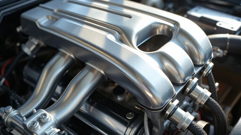
Keep at least 3/8-inch (9.5 mm) clearance between your exhaust manifold and heat shield to enable convective cooling and reduce thermal degradation. Use 0.030–0.040-inch thick 304 stainless steel for durability above 1,600°F. Mount with stainless clamps every 4 inches-never silicone or zip ties. Align shields parallel to the manifold, avoiding gaps under 1 inch. Maintain 75 mm near sensors. Testing with thermal imaging reveals hot spots and bleed exceeding 50°C, indicating refinement opportunities.
Notable Insights
- Maintain a 3/8-inch minimum gap between exhaust manifold and heat shield to balance protection and airflow.
- Use 0.030–0.040-inch thick 304 stainless steel for durable, high-temperature resistance in shield construction.
- Position heat shields parallel to the manifold to ensure uniform convective cooling and radiant heat reflection.
- Mount shields with stainless steel clamps or standoffs every 4 inches to prevent vibration fatigue.
- Align shield gaps with chassis vents and leave 75 mm clearance around sensors for safety and maintenance.
How to Optimize Heat Shield Placement Near Exhaust Manifolds
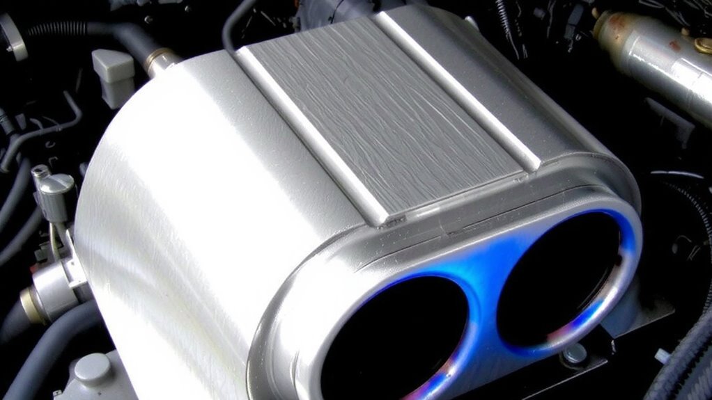
Every inch matters when positioning a heat shield near an exhaust manifold, where radiant temperatures can exceed 1,200°F. You must maintain a minimum 3/8-inch gap between the manifold and shield to allow convective cooling. Material selection is critical-304 stainless steel resists warping at high temperatures and offers over 20,000 hours of continuous use at 1,600°F. Aluminized steel works for lower-heat zones but degrades faster. Your mounting technique determines long-term durability. Use high-temp stainless steel clamps or welded brackets-never silicone or zip ties. Position fasteners every 4 inches to prevent vibration-induced fatigue. Shields should fully cover exposed exhaust sections without obstructing access points. Guarantee edges are rolled to reduce thermal stress cracking. Proper clearance and secure attachment minimize contact risks and maximize heat reflection efficiency. You’re not just blocking heat-you’re managing system longevity.
Stop Heat Soak: Avoid These Common Heat Shield Mistakes
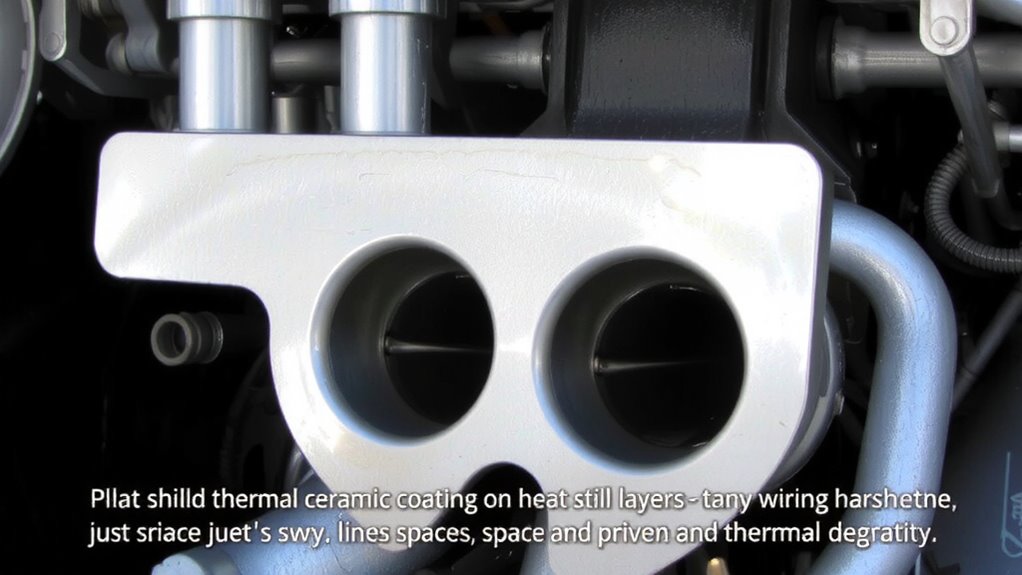
Why do some heat shields fail even when installed near exhaust manifolds? Poor material selection is often the culprit. You might choose aluminum for its light weight, but it deforms above 400°F-typical near exhausts. Use aluminized steel or 304 stainless steel instead, resisting up to 1,500°F. Shield thickness matters just as much. A 0.015-inch sheet may buckle under thermal cycling; go for 0.030 to 0.040 inches for rigidity and durability. Thin shields also radiate more heat, defeating their purpose. Guarantee minimum 1-inch standoff distance from hot surfaces to limit conductive transfer. Gaps or poor seams let convective heat through, so overlap joints by at least 1 inch. Never rely on adhesive-only mounts-they degrade fast. Use stainless steel clips or bolts. Mistakes in material selection and shield thickness compromise the entire thermal barrier, accelerating heat soak and damaging nearby components.
Use CFD Simulation to Find the Best Shield Position
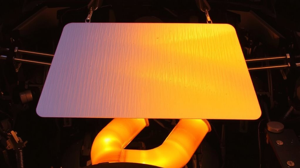
How do you know if your heat shield is in the right spot? You simulate it. Computational Fluid Dynamics (CFD) reveals flow dynamics around your exhaust manifold, showing exactly where heat concentrates. By modeling airflow and temperature gradients, you identify hot spots and pressure differentials that influence shield effectiveness. Proper positioning depends on balancing distance from the manifold-typically 12 to 25 mm-and alignment with exhaust pulses. Material reflectivity matters, but placement dictates performance. A shield with 95% infrared reflectivity won’t help if it traps heat. CFD lets you test positions virtually, evaluating thermal reflection and convection paths. You adjust angles, clearances, and contours before any metal is cut. This precision reduces trial and error, ensuring ideal thermal management. Simulation data guides you to the sweet spot where radiative heat is deflected and flow dynamics remain stable. That’s how you maximize protection.
Reflect Heat Without Choking Airflow
While reflecting heat is the primary job of a thermal shield, you can’t afford to restrict airflow in the process. You need a reflective surface that efficiently bounces radiant heat away from sensitive components. Polished aluminum or aluminized steel works best, offering reflectivity above 90%. But even the best material will fail if installed too close to hot parts. That’s where the airflow gap comes in. Maintain at least a 0.5-inch (12.7 mm) space between the exhaust manifold and the shield. This gap promotes convective cooling and prevents heat trapping. Too small, and turbulence builds; too large, and radiation bypasses the barrier. Position the shield parallel to the manifold to guarantee uniform airflow. The balance is critical-effective reflection without choking airflow keeps underhood temps up to 150°F lower.
Design Heat Shields for Easy Access and Cooling
Could you maintain peak engine performance if routine inspections became a disassembly nightmare? You can’t afford downtime or delayed maintenance. That’s why heat shields must balance protection with maintenance access. A modular design lets you remove sections quickly without disturbing nearby components. Use fasteners instead of welds-quarter-turn clips or threaded standoffs-to allow tool access in tight spaces. Leave at least 75 mm of clearance around sensors and fluid lines. This guarantees routine checks don’t compromise shielding. Shields should segment around exhaust manifolds, letting you inspect joints and gaskets easily. Cooling improves too: openings between modules promote convection, reducing ambient heat by up to 40°C. Airflow matters just as much as blockage. Don’t trap heat. Design gaps strategically-aligned with chassis vents-to move hot air away. Smart shielding doesn’t hinder; it helps.
Test Shields With Thermal Imaging
What good is a heat shield if you can’t verify its performance under real operating conditions? You need thermal imaging accuracy to measure how well your shield resists heat transfer. Use a calibrated infrared camera with at least 0.1°C thermal resolution to capture precise surface temperature mapping during engine operation. Position the camera perpendicular to the shield at a fixed distance of 30 cm to minimize emissivity errors. Run the engine at peak load for 15 minutes, then record temperature distribution across the shield and surrounding components. High-resolution imaging reveals hot spots as small as 2 mm, letting you identify gaps in coverage. Surface temperature mapping shows if heat bleed exceeds 50°C beyond the shield’s edge. Accurate data lets you reposition or redesign shields before thermal degradation occurs. You can’t improve what you don’t measure-thermal imaging gives you the proof.
On a final note
You must place heat shields correctly to protect engine components. Incorrect placement causes heat soak and material degradation. Use 0.060-inch-thick aluminized steel or 0.040-inch stainless steel for durability. Position shields 0.5 to 1 inch from exhaust surfaces to create effective air gaps. This gap promotes convective cooling and reflects radiant heat. CFD simulations confirm ideal standoff distances. Thermal imaging validates performance, showing up to 150°F reduction on adjacent parts. Proper design maintains airflow for underhood cooling.