How to Replace a Blown Charging System Warning Light Bulb
Turn off the ignition and disconnect the battery’s negative terminal to prevent shorts. Use a Phillips screwdriver and plastic trim tool to remove the dashboard cover and access the instrument cluster. Locate the charging warning bulb-typically a 1.5V, 50 mA wedge-base type near the battery symbol. Replace it with an identical incandescent or LED equivalent, ensuring proper seating. Test with ignition “on”; the light should glow steadily. Further diagnostics await if issues persist.
Notable Insights
- Disconnect the battery’s negative terminal to ensure safety before starting the replacement process.
- Remove the instrument cluster by taking off dashboard trim and unscrewing mounting screws with a Phillips screwdriver.
- Locate the charging system warning light bulb near the battery symbol on the cluster’s circuit board.
- Extract the old bulb using non-metallic tweezers and insert a compatible replacement straight into the socket.
- Reconnect power, turn the ignition to “ON”, and verify the warning light illuminates for 1–3 seconds.
Test the Charging System Warning Light
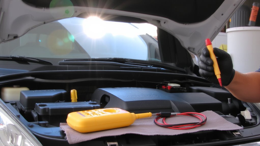
Ever wonder why your charging system warning light doesn’t come on when you turn the key to “run”? This simple test confirms bulb functionality before deeper electrical diagnosis. When the ignition engages “run,” the light should illuminate for 1–3 seconds, drawing power through a resistor in the alternator’s field circuit. No illumination suggests a failed bulb, open circuit, or faulty alternator. Begin with a basic circuit inspection: check the fuse, then verify voltage at the instrument cluster. Use a digital multimeter to test for 12V at the bulb socket. Open circuits often stem from corroded contacts or broken traces. A working bulb confirms the warning system is active; absence demands further electrical diagnosis. Continuity checks along the control path isolate faults. Never assume bulb failure-verify. This step saves time and guarantees accurate troubleshooting.
Gather Tools to Replace the Bulb
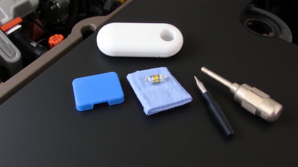
You’ll need a few essential tools to replace the charging system warning light bulb safely and efficiently. Start with a set of precision screwdrivers-particularly a #1 Phillips and a 5mm flathead-for delicate dashboard work. Include a plastic trim removal tool to prevent damaging interior panels. Always follow safety precautions: disconnect the battery’s negative terminal before starting. This prevents electrical shorts and protects sensitive components. Use gloves and safety glasses to shield against debris. Confirm the correct bulb types by checking your vehicle’s service manual-common types include 74, 168, or 194 incandescent bulbs, or LED equivalents. Verify replacement bulbs match voltage ratings-typically 12V-and base type, such as T10 or wedge base. A multimeter helps verify continuity in new bulbs. Keep all tools organized to minimize errors and streamline the process.
Remove Dashboard to Access Charging Light
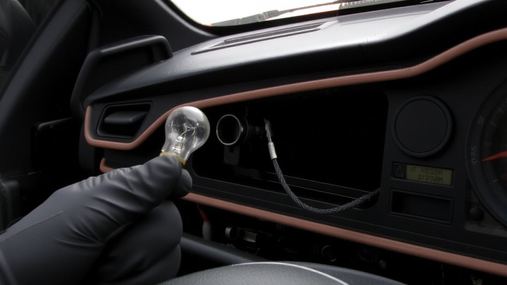
Begin by removing the lower steering column cover to gain access to the instrument cluster. Use a trim removal tool to carefully pry off the dashboard trim without damaging the plastic clips. Once the trim is loose, locate the screws securing the instrument panel and remove them with a Phillips screwdriver. Gently pull the dashboard forward to expose the back of the cluster. Disconnect all electrical connectors by pressing the release tabs and pulling them straight out-don’t yank. Each connector corresponds to specific systems, so note their positions. The instrument cluster typically measures 8 x 4 inches and weighs about 2.5 pounds. Handle it by the edges to avoid damaging internal circuits. Make sure the ignition is off and the key is removed to prevent electrical shorts. This step gives you direct access to the cluster housing, preparing for the next phase.
Find the Charging System Warning Light Bulb
The charging system warning light bulb is typically located on the printed circuit board behind the instrument cluster faceplate. Accurate location identification is essential, as multiple bulbs serve different gauges and indicators. Look for a small, wedge-base bulb (usually 1.2V to 1.5V, 25–50 mA) near the battery-shaped or “CHARGE” symbol. Use a wiring diagram specific to your vehicle model for precise positioning-variances exist between manufacturers. Perform thorough bulb inspection by visually examining the filament under good lighting; a broken or sagging filament indicates failure. Avoid confusing it with nearby bulbs such as oil pressure or low fuel indicators. Use a magnifying glass if necessary. Do not apply pressure to the circuit board. Confirm bulb orientation before removal to guarantee correct replacement. Location and condition verification during inspection minimizes diagnostic errors and prevents unnecessary part replacement.
Replace the Charging Light Bulb
Once you’ve confirmed the faulty bulb’s location and orientation, carefully remove it using a small plastic bulb extractor or clean, non-metallic tweezers to avoid damaging the socket. Insert the replacement bulb straight in to prevent misalignment. Proper handling guarantees dashboard aesthetics remain pristine and electrical contact stays secure.
| Bulb Type | Voltage | Average Lifespan |
|---|---|---|
| Incandescent | 12V | 1,500 hours |
| LED (Standard) | 12V | 30,000 hours |
| Neon | 12V | 8,000 hours |
| Halogen | 12V | 2,000 hours |
| SMD LED | 12V | 50,000 hours |
Using high-quality bulbs enhances bulb longevity and reduces future maintenance. Match the replacement to your vehicle’s specifications exactly. A well-installed bulb maintains maximum brightness and alignment, preserving both function and dashboard aesthetics. Avoid touching halogen bulbs with bare hands-oil residue can create hot spots and shorten lifespan.
Test the Charging System Warning Light
After replacing the bulb, you’ll want to verify the charging system warning light works correctly before closing up the dashboard. Turn the ignition to the “ON” position without starting the engine. The warning light should illuminate steadily. This confirms circuit continuity from the battery, through the warning light, and to the voltage regulator. If the light doesn’t turn on, check for open circuits or poor connections in the fuse panel and instrument cluster. A multimeter test can verify voltage output at the bulb socket-expect battery voltage, typically 12.6 volts. Proper illumination indicates the circuit is intact and the bulb received adequate power. This test doesn’t assess alternator performance-only that the warning light circuit is functional. Confirming voltage output and circuit continuity guarantees the system will alert you if charging issues arise later. Never skip this step.
When Charging Light Issues Aren’t Just a Bulb
Why does your charging system warning light stay on even after replacing the bulb? The issue likely isn’t the bulb at all. A persistent light often signals deeper problems like alternator failure or a faulty voltage regulator. The alternator generates electrical power while the engine runs, typically outputting 13.5 to 14.5 volts. If voltage drops below or spikes above this range, the warning light activates. A failing alternator can’t sustain proper output, starving the battery and electrical systems. The voltage regulator controls this output, preventing overcharging or undercharging. If it malfunctions, the entire charging system becomes unstable. Diagnose with a multimeter: measure voltage at the battery with the engine running. Consistent readings outside 13.5–14.5V confirm alternator failure or voltage regulator issues. Don’t ignore it-prolonged undercharging damages the battery and risks breakdowns.
On a final note
Now the charging system warning light works correctly. A properly functioning bulb guarantees accurate monitoring of the vehicle’s electrical output. The bulb typically uses a 12-volt, 1.7-watt miniature wedge base (T10). Verify fitment with your vehicle’s service manual. Reassemble the dashboard securely. Fasteners torque to 1.5–2.0 Nm. Test operation by turning the ignition to “ON” without starting. The light must illuminate steadily, confirming circuit integrity.