How to Use a Car Audio Analyzer to Diagnose Speaker Issues
Turn off your car audio before connecting the analyzer to speaker outputs or RCAs with shielded cables. Set input to speaker or line level, then calibrate using a 1 kHz reference tone. Monitor impedance-most car speakers are 4 ohms; dips below or spikes above indicate shorts or open coils. Check frequency response for smooth curves; jagged dips near 50–100 Hz suggest mechanical damage. Real-time THD over 10% or clipped waveforms confirm failure. You’ll find how to act on these results next.
Notable Insights
- Turn off the car audio system before connecting the analyzer to prevent electrical damage.
- Connect the analyzer to speaker or preamp outputs using matching impedance and shielded cables.
- Check impedance at 1 kHz; readings significantly below or above rated ohms indicate speaker damage.
- Analyze frequency response for dips or jagged curves, which suggest cone tears or mechanical faults.
- Monitor real-time THD and waveform clipping to detect distortion and prevent further speaker damage.
How a Car Audio Analyzer Detects Speaker Damage
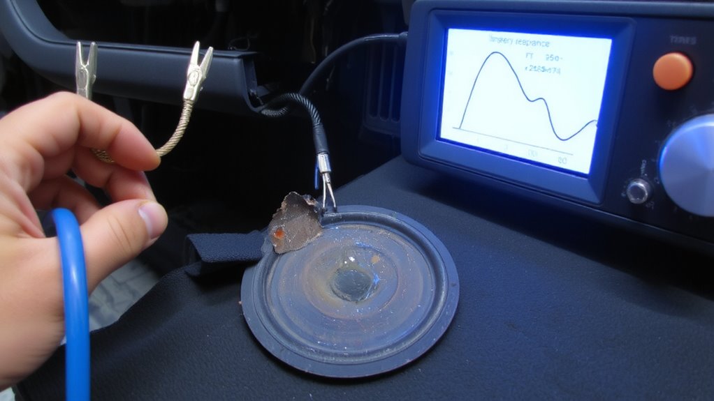
Fault detection in car audio systems starts with impedance and frequency response measurements-key indicators of speaker health. You’ll see abnormal impedance dips below the rated ohms, often signaling voice coil damage or speaker burn. A healthy speaker typically shows a peak impedance at resonance between 30–100 Hz, depending on design. Deviations here suggest mechanical faults like a rubbing coil or misalignment. Frequency response analysis reveals output drops in specific ranges; a sharp decline in mid-bass frequencies often points to a cone tear. That physical rupture disrupts pistonic motion, causing distorted sound and reduced efficiency. You can identify this by a jagged response curve instead of a smooth roll-off. Total harmonic distortion (THD) readings above 10% at normal volumes further confirm damage. These measurements, combined, give you objective evidence of degradation-no guesswork needed.
Connect a Car Audio Analyzer to Your Stereo
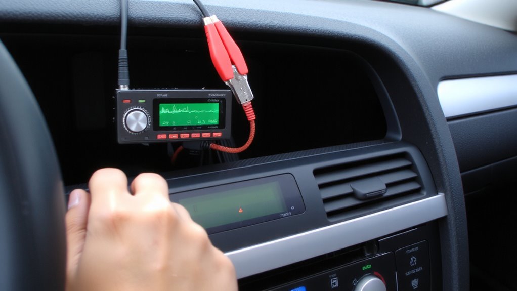
Start by turning off your car’s audio system to prevent electrical surges during connection. Locate your stereo’s speaker output wires or RCA preamp outputs, depending on your setup. Use matching impedance and shielded cables to link the analyzer to the stereo’s output channels. Secure all connections tightly to avoid signal loss. Set your analyzer’s input selection to match the source-speaker level or line level-based on how you’re tapping the signal. Improper input selection can distort readings or damage equipment. Perform signal calibration by sending a reference tone, usually 1 kHz at 0 dB, through each channel. The analyzer uses this baseline to guarantee measurement accuracy across frequency response and impedance tests. Calibration adjusts for system-specific variables, just like zeroing a scale before weighing. Always confirm voltage ratings and impedance loads align with your analyzer’s specifications to avoid equipment damage.
Read Frequency and Impedance to Diagnose Speakers
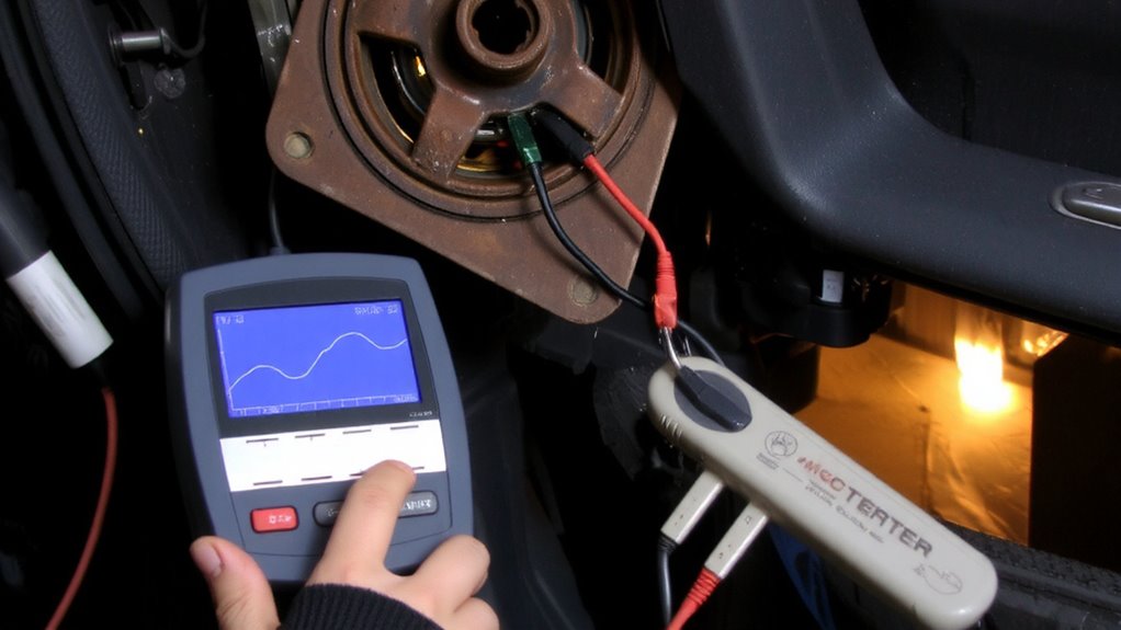
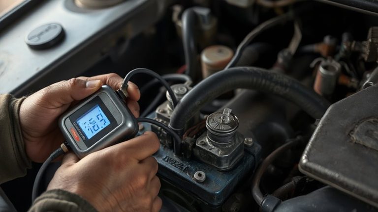
Your speaker’s performance lives in the numbers-frequency response and impedance reveal the truth behind the sound. Frequency response shows how well your speaker reproduces tones from low bass to high treble, typically measured in hertz (Hz). A healthy speaker maintains a smooth response curve within its rated range, like 50 Hz to 20,000 Hz. Deviations indicate damage or design flaws. Impedance, measured in ohms, reflects electrical resistance. Most car speakers are 4 ohms; amps expect this load. An impedance mismatch strains your amplifier, risking overheating or shutdown. Use your analyzer to check impedance at 1 kHz-it should stay close to the rated value. Wild swings suggest a failing voice coil or damaged surround. Comparing both frequency response and impedance helps isolate mechanical from electrical faults. You’re not guessing-you’re measuring.
Catch Distortion in Real Time With Audio Analysis
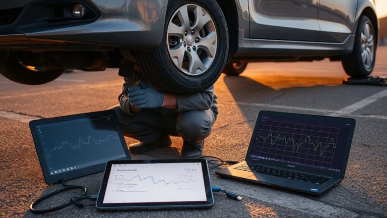
A clean signal turns muddy when distortion enters the equation, and that’s where real-time audio analysis becomes your diagnostic lens. With real time monitoring, you observe waveform integrity as it happens, spotting anomalies before they damage components. Signal clipping appears as flattened waveform peaks, a clear indicator the amplifier can’t handle input demands. Your analyzer displays this instantly, often with voltage thresholds-like 1% THD-flagging distortion onset. Most systems clip above 0.5% total harmonic distortion, but car environments tolerate slightly higher due to noise. Use the analyzer’s oscilloscope function to compare expected vs. actual output. A clipped signal stresses voice coils and invites thermal failure. Monitoring in real time lets you adjust gain settings or EQ to restore headroom. Proper signal integrity guarantees speakers receive clean power within rated limits. You don’t guess-you verify. Distortion caught early preserves sound quality and extends speaker life.
Fix Speaker and Wiring Problems Identified by Analysis
Once the audio analyzer flags an issue, you can’t just tweak settings and hope it resolves-the problem might be in the speaker or wiring, and both demand methodical correction. Check connections first; loose or corroded wires cause distortion and impedance mismatches. Verify phase alignment: reversed polarity leads to cancellations, especially in bass response. Use the analyzer’s polarity test to confirm all speakers move in unison. Examine power handling: if amplifiers deliver more wattage than speakers can manage, drivers fail prematurely. Match RMS ratings closely to avoid damage.
| Issue | Solution |
|---|---|
| Phase misalignment | Reverse speaker leads or adjust DSP settings |
| Overdriven speakers | Reduce amplifier gain to match speaker power handling |
| High impedance reading | Check for broken voice coils or loose wiring |
| Low impedance reading | Inspect for short circuits in wiring harness |
Replace damaged components, then retest with the analyzer.
On a final note
You now have the tools to pinpoint speaker faults accurately. A car audio analyzer measures impedance, frequency response, and distortion levels in real time. Typical voice coil impedance is 4Ω or 8Ω; deviations indicate shorts or open circuits. Frequency sweeps reveal response gaps-such as a blown tweeter missing output above 8 kHz. Real-time distortion readings above 1% THD suggest clipping or damage. Use this data to replace faulty components or repair wiring. Precision diagnostics guarantee peak sound.