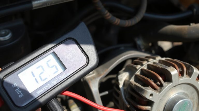
Advanced Techniques for Diagnosing and Repairing Electrical Issues in Your Vehicle’s Charging System: From Alternator to Battery
Test your alternator’s output with a multimeter at the battery: expect 13.8–14.4V DC under load. Voltage below 13.5V means charging failure; over 14.8V points to regulator issues. Check for parasitic draw by measuring current in series-normal is under 50mA after systems sleep. Clean grounds to bare metal, tighten to 8–10 ft-lbs, and verify voltage drop stays under 0.1V. Inspect cables for strand loss, corrosion, or >0.5V drop under load. A 0.8V drop in a ground strap can cripple charging efficiency. Master these diagnostics, and you’ll uncover what hides beneath surface symptoms.
Notable Insights
- Test alternator output voltage at the battery under load, ensuring it stays within 13.8–14.4V to confirm proper charging.
- Measure key-off parasitic draw in series with the negative terminal, isolating faulty circuits by pulling fuses after system sleep.
- Inspect and clean all ground connections, ensuring resistance is below 0.5 ohms and voltage drop does not exceed 0.1V.
- Use wiring diagrams to trace circuits, verify signal voltages at the alternator B+ terminal, and test continuity in suspect wires.
- Perform voltage drop tests on charging cables under load; replace if drop exceeds 0.5V or physical damage is evident.
Test Your Alternator Output in Minutes
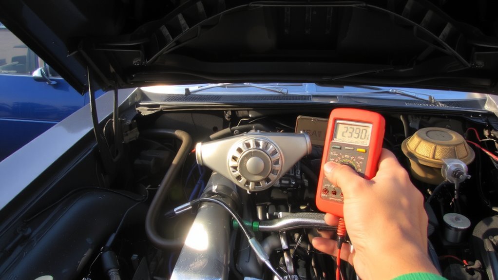
A multimeter is your first line of defense when checking alternator output-think of it as a stethoscope for your car’s electrical system. You’ll measure alternator voltage directly at the battery terminals while the engine runs. Set your multimeter to DC volts, then connect the red probe to the positive terminal and the black to the negative. A healthy charging system reads between 13.8 and 14.4 volts. That’s your alternator voltage in the ideal range. Output testing under load reveals performance issues. Turn on headlights, HVAC, and radio-voltage should stay stable. If it drops below 13.5, your alternator can’t sustain output. If it exceeds 14.8, the voltage regulator may be failing. Consistent readings confirm proper alternator function. Inaccurate output damages batteries and electronics. Test yearly, or if you notice dimming lights. This quick check saves costly repairs down the road.
Find Hidden Charging System Drains in 3 Steps
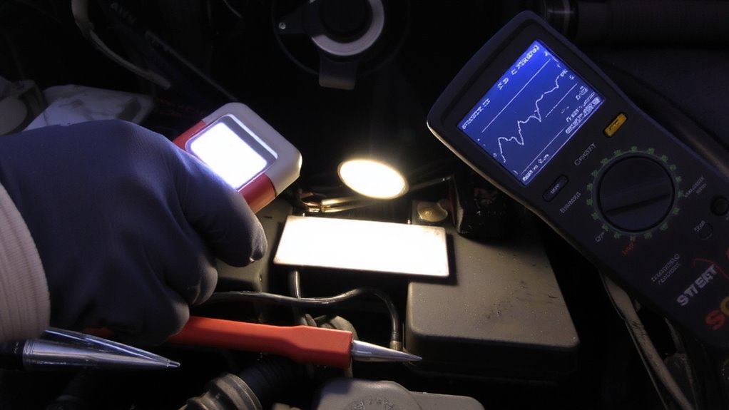
How much current should your vehicle draw with the key off? Less than 50 milliamps is normal. Anything higher indicates a parasitic draw draining your battery. First, set your multimeter to measure DC current and connect it in series between the negative battery terminal and ground. Wait 15–20 minutes for modules to power down. If the reading stays above 50 mA, you’ve got a problem. Second, pull fuses one at a time while monitoring the meter. When current drops, you’ve found the circuit causing the drain. Third, inspect that circuit for faulty components, like a stuck relay or malfunctioning module. A significant voltage drop across connections can also point to high resistance, worsening the issue. Check wiring and connectors thoroughly. Fixing parasitic draw prevents unexpected battery failure and guarantees system efficiency.
Fix Charging System Ground Connection Problems
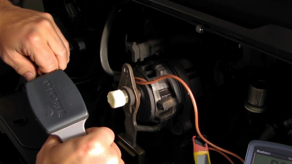
That ground connection isn’t just a backup path-it’s a critical part of your vehicle’s charging system. A poor ground increases electrical resistance, reducing charging efficiency and stressing components. You’ll often find corroded terminals on the battery or engine block, especially in humid environments. Corrosion creates a resistive layer-sometimes exceeding 0.5 ohms-disrupting current return paths. Clean all contact surfaces with a wire brush until bare metal shows. Apply dielectric grease to prevent future corrosion. Check for loose straps connecting the battery to the chassis and engine. A loose strap can cause voltage drops over 0.3 volts, well above the acceptable 0.1-volt limit. Tighten mounting bolts to manufacturer specs-typically 8–10 ft-lbs. Guarantee strap integrity: frayed or broken strands reduce conductivity. A solid ground ensures stable voltage regulation and protects sensitive electronics.
Decode Wiring Diagrams to Find Electrical Faults
Why do some electrical issues seem impossible to trace? Because without a wiring diagram, you’re guessing. You need circuit tracing to follow current paths from the alternator to the battery and beyond. Wiring diagrams show wire colors, gauge sizes-typically 10 to 16 AWG-and connector locations critical for accuracy. Use signal testing to confirm voltage presence at key nodes: at the alternator output (B+ terminal), voltage should be 13.8–14.7V when running. Compare readings to diagram specifications. A break in continuity or unexpected resistance-over 0.5 ohms-indicates a fault. With circuit tracing, you isolate open circuits or shorts using a multimeter. Signal testing verifies sensor and regulator communication, often through 5V reference lines. Diagrams map ground points too, so verify them. Never assume wire function-read the diagram. It removes guesswork. You’ll diagnose faster and fix faults right the first time.
Inspect and Replace Damaged Charging Cables
Start by visually inspecting the entire length of the charging cables, especially near the alternator output (B+), battery terminals, and ground connections. Look for cracked or brittle cable insulation-damaged sheathing exposes conductors to shorts and voltage leaks. Fraying or melted spots indicate overload or chafing against metal components. Check for connector corrosion, particularly on the B+ terminal and ground lugs; white, green, or blue crust means oxidation is increasing resistance. Use a multimeter to confirm voltage drop across cables-anything over 0.5V under load signals trouble. If you find swelling, pitting, or more than 20% wire strand loss, replace the cable. Use OEM-spec gauge wire-typically 4 to 2 AWG-for proper current handling. Heat-resistant, cross-linked polyethylene insulation guarantees longevity. Always disconnect the battery before replacement.
Why Your Charging System Fails Without Warning
What makes a charging system fail suddenly, even when it seemed fine minutes before? Voltage spikes can overwhelm sensitive circuits without warning. These surges, often exceeding 15 volts during operation, damage regulators and degrade diodes inside the alternator. Over time, component aging weakens internal windings and brushes, reducing efficiency. A worn alternator might still output 13.5 volts at idle but collapse under load. The battery may seem healthy but can’t compensate when the charging system fails. Wiring insulation also deteriorates, increasing resistance and fire risk. Modern vehicles depend on stable 14.2–14.7-volt ranges; deviations above or below disrupt ECU function. A failing voltage regulator often shows no symptoms until it stops working entirely. Regular voltage drop tests across cables and connections help catch issues early. Don’t wait for total failure-inspect for corrosion, measure output under load, and replace parts showing signs of wear. Prevention beats breakdown.
On a final note
You now have the tools to diagnose and fix charging system issues quickly. Test alternator output: it should produce 13.8–14.7 volts at idle. A parasitic drain over 50 milliamps indicates a fault. Poor ground connections cause voltage drops; guarantee resistance is below 0.1 ohms. Inspect cables for fraying or corrosion. Use wiring diagrams to trace faults accurately. Proper maintenance prevents sudden failures.