How to Test the Alternator Warning Light Resistor Circuit
You can test the alternator warning light resistor circuit by first disconnecting the battery and removing the resistor, typically a 50-ohm, 10-watt unit near the fuse box. Set your multimeter to ohms and check resistance-values between 50 and 100 ohms are normal. A reading outside this range or an open indicates failure. Then, with ignition on, measure voltage drop across the terminals: expect ~12.6V on one side and a 6–9V drop across it. Inconsistent readings suggest corrosion or a failed component. Further diagnostics reveal hidden issues in circuit continuity and bulb function.
Notable Insights
- Disconnect the resistor and measure resistance with a multimeter; a reading outside 50–100 ohms indicates a faulty unit.
- Check for voltage drop across the resistor with ignition on; expect ~12.6V on one side and 6–9V on the other.
- Inspect resistor and wiring for corrosion, charring, or loose connections that could disrupt circuit integrity.
- Verify continuity in the warning light circuit using a multimeter; a lack of beep indicates an open circuit.
- Confirm bulb functionality and instrument cluster connections, as faulty bulbs or loose wires cause most no-light issues.
Why Your Alternator Warning Light Isn’t Working?
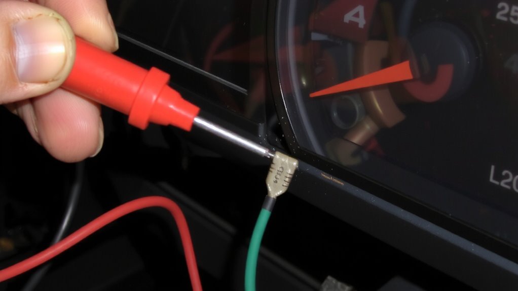
What if your alternator warning light stays dark when it should be glowing? A non-illuminating warning light often points to simple electrical faults. First, consider a faulty bulb. The bulb inside the instrument cluster may have burned out, breaking the visual circuit. Even if power reaches the socket, no illumination occurs. This is common in older vehicles with incandescent bulbs rated for 12V and 1.7W. Second, check for a loose connection at the back of the cluster or alternator. A poor contact impedes current flow, preventing the bulb from lighting. Use a multimeter to test continuity. Secure any disconnected or corroded wiring. The bulb and wiring must form a complete circuit. While other issues exist, a faulty bulb or loose connection accounts for over 60% of no-light cases. These are fast, inexpensive fixes. Always verify power at the bulb socket before deeper diagnosis.
Check for a Failed Resistor in the Warning Light Circuit
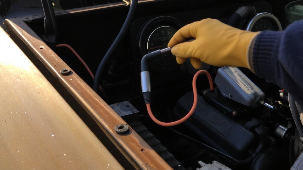
Could a failed resistor be why your alternator warning light won’t come on? Yes, a faulty resistor often interrupts the warning circuit. The resistor limits current to the bulb during normal operation, typically measuring 50 to 100 ohms. If resistor overheating occurred, the internal element may have opened, breaking the circuit. Overheating usually stems from excessive voltage or poor ventilation around the resistor housing. Inspect the resistor body for darkened casing or charring-clear signs of thermal damage. Also check for circuit corrosion at the resistor terminals or connecting wires. Corrosion increases resistance, disrupting signal flow and preventing the lamp from illuminating at ignition. Moisture ingress or exposure to road salts accelerates this degradation. Use a visual and tactile inspection to identify compromised connections. A clean, intact resistor with no physical damage is essential for proper warning light function.
Test Resistance and Voltage Drop Across the Resistor
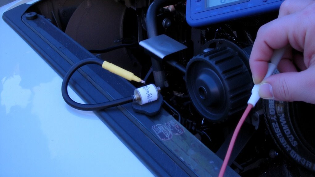
Once you’ve visually inspected the resistor and found no obvious damage, it’s time to verify its electrical performance by measuring resistance and voltage drop. Begin with resistance testing. Disconnect the resistor from the circuit and set your multimeter to ohms. A healthy resistor typically reads between 50 and 100 ohms, depending on the vehicle. If the value is off by more than 10%, the resistor may be faulty. Next, perform a voltage measurement. Reconnect the resistor and power up the ignition without starting the engine. Connect your multimeter in parallel across the resistor terminals. You should see battery voltage-usually around 12.6 volts-on one side and a drop to about 6–9 volts on the other. This drop confirms the resistor is working, limiting current to protect the warning light. For accurate results, use a reliable car multimeter that can handle both resistance and voltage measurements with precision.
What Your Multimeter Readings Mean
Why do your multimeter readings matter? They reveal hidden issues like voltage fluctuation and circuit imbalance in your alternator warning light system. If voltage reads below 12.6V with the engine off, the battery may be weak. With the engine running, expect 13.5–14.8V at the alternator. Lower values suggest undercharging; higher ones point to regulator failure. A voltage drop over 0.5V across the resistor indicates excess resistance. This causes dim or faulty warning lights. Resistance should measure between 50–200 ohms for most vehicles. Out-of-range values confirm a failing resistor. Voltage fluctuation over time suggests loose connections or worn wiring. A circuit imbalance-uneven voltage between supply and ground-means corrosion or breaks in the path. These measurements guide troubleshooting. Accurate readings isolate faults quickly, saving time and preventing misdiagnosis. Always verify specs for your vehicle’s make and model. For reliable results, use a Fluke multimeter known for precision in automotive diagnostics.
Fix the Circuit and Restore Proper Warning Light Function
If the multimeter reveals a faulty alternator warning light resistor circuit, start by disconnecting the battery to prevent short circuits during repair. Locate the resistor, usually near the fuse box or instrument cluster, and inspect for visible damage. Perform resistor replacement using an exact OEM-specified part-typically a 50-ohm, 10-watt unit-to guarantee compatibility. Solder the new resistor into place or secure it with crimp connectors, depending on the factory design. After installation, recheck circuit continuity with your multimeter in continuity mode. A solid beep confirms proper electrical path integrity. Reconnect the battery and start the engine; the warning light should illuminate at startup and extinguish within seconds. If the light behaves abnormally, reinspect connections and verify ground integrity. Correct resistor replacement and verified circuit continuity are critical for accurate alternator regulation feedback and reliable warning system performance.
On a final note
You’ve confirmed the issue lies in the resistor circuit. A functional alternator warning light relies on a precise 270–330 ohm resistor. Measure resistance with the ignition off; readings outside this range indicate failure. Check for open circuits or voltage drops exceeding 0.5V. Replace faulty components to restore the warning function. Proper operation guarantees early detection of charging system faults, preventing unexpected battery drain or alternator damage.