Using a Multimeter to Measure Alternator Warning Light Voltage
You can check the alternator warning light voltage by setting your multimeter to DC volts and connecting the red probe to the light’s terminal, the black to ground. With the ignition on and engine off, you should see 12.0–12.6V. If the voltage is lower, there may be circuit resistance or a weak battery. Once the engine runs, voltage at the light should drop to near 0V-indicating proper alternator function. A reading that stays high means the alternator isn’t charging. Normal system voltage while running is 13.5–14.8V. Over 14.8V suggests overcharging; below 13.5V means undercharging. Issues like corroded connections or a failing voltage regulator often cause these faults. Understanding these values helps pinpoint whether the problem lies in the alternator, wiring, or control circuit. Further analysis reveals deeper electrical behavior.
Notable Insights
- Set your multimeter to DC voltage below 20V and confirm test leads are intact for accurate readings.
- Measure battery voltage at the warning light terminal with ignition on (engine off); expect 12.0–12.6V.
- A reading below 11V with ignition on suggests circuit resistance or poor connection issues.
- After starting the engine, voltage at the warning light should drop to near 0V if the alternator is working.
- If the warning light stays lit and shows ~12.6V while running, the alternator isn’t charging the system.
What Triggers the Alternator Warning Light?
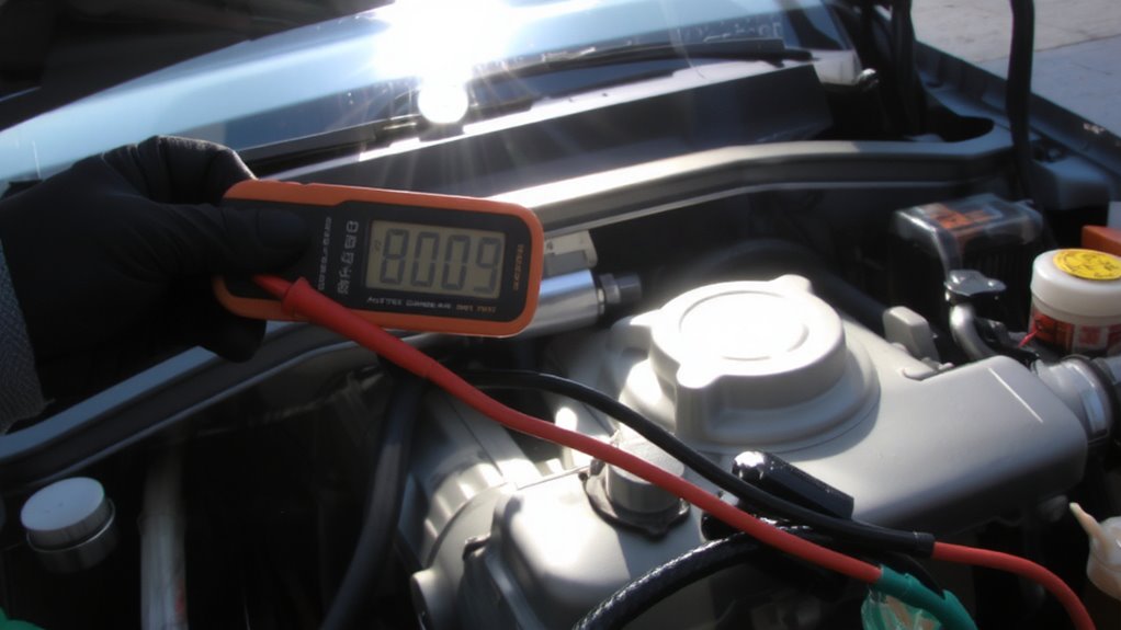
Why does the alternator warning light suddenly glow on your dashboard? It typically signals a charging system fault. When you turn the ignition switch to “on,” the warning light briefly illuminates as part of a self-check. It should extinguish after the engine starts. If it stays lit, your alternator isn’t producing adequate voltage. This leads to insufficient battery charging and eventual battery drain. The light activates when system voltage drops below 13.5 volts or rises above 14.8 volts. A failed diode, worn brushes, or a slipping drive belt can cause this. Battery drain occurs because the electrical load is then drawn directly from the battery. Without correction, voltage drops below 12.0 volts, causing electronics to fail. The ignition switch position is critical-light behavior in “run” versus “start” helps diagnose if the issue is in the alternator, regulator, or warning circuit.
Normal Alternator Warning Light Voltage
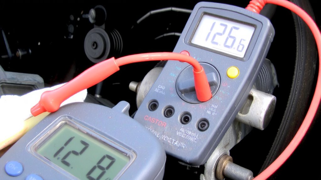
The alternator warning light behaves predictably under normal conditions, and understanding its voltage range helps confirm system health. When the engine is off, you’ll typically see battery voltage-around 12.6V-applied to the warning light circuit. Once the engine runs, alternator output increases system voltage to 13.5–14.8V, causing the warning light to turn off. This voltage shift confirms proper alternator function and supports long-term battery health. A steady-on or flickering light suggests a charging problem. Below is a reference table showing typical voltage readings:
| Condition | Warning Light Voltage |
|---|---|
| Engine off | ~12.6V |
| Engine running | ~0V (light off) |
| Alternator fault | ~12.6V (light on) |
| Voltage regulator fail | Fluctuating |
Monitoring this circuit helps diagnose alternator output and battery health efficiently.
Multimeter Setup for Alternator Warning Light Testing
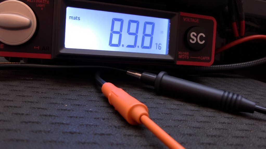
How do you guarantee your multimeter is ready to diagnose alternator warning light issues accurately? Start by selecting a digital multimeter with at least 10 MΩ input impedance and accuracy within ±0.5%. Set the dial to DC voltage (20V range). Perform a continuity check on the test leads by touching the probes together-your meter should beep and show near-zero ohms, confirming intact internal circuitry. Faulty leads cause false readings. Make sure probe placement is secure and clean; use needle-tipped probes to pierce insulation if necessary, but avoid damaging wires. Calibrate the multimeter if prompted. Verify battery strength-low power skews results. Always connect red to positive and black to ground. Proper setup ensures precise detection of voltage anomalies before live testing begins. Accuracy here eliminates guesswork in diagnosing circuit faults. For reliable performance, choose one of the top car multimeters recommended for automotive diagnostics.
Measuring Alternator Warning Light Voltage
You’ve confirmed your multimeter is properly configured-now it’s time to measure the voltage at the alternator warning light circuit directly. Set your multimeter to DC voltage with the range below 20 volts. Connect the black probe to a solid ground and the red probe to the warning light terminal on the alternator or instrument cluster. Turn the ignition key to “ON” without starting the engine. You should read battery voltage-typically 12.0 to 12.6 volts. A significant voltage drop-below 11 volts-may indicate resistance in the circuit. This can lead to improper charging or even battery drain over time. Verify connections are clean and tight. A steady reading near battery voltage confirms the warning light circuit is intact. Avoid prolonged key-on periods without engine operation to reduce risk of battery drain. Record your reading for comparison in the next diagnostic step.
What Your Multimeter Reading Means
While voltage readings might seem straightforward, interpreting them correctly is key to diagnosing alternator issues accurately. A正常 reading indicates proper charging, but deviations suggest problems like battery drain or faulty wiring. Your multimeter’s value reflects system health under specific conditions.
| Voltage Reading | Interpretation |
|---|---|
| 12.6V or below | Battery is discharged; possible battery drain |
| 13.8–14.4V | Normal charging; system functioning correctly |
| Above 14.4V | Overcharging; could indicate faulty wiring or regulator |
Readings below 12.6V often mean the alternator isn’t charging. This can leave you stranded. Values over 14.4V stress the battery and may damage electronics. Consistent monitoring helps catch issues early. Faulty wiring often causes unstable voltage. Always test with the engine running to assess real-time performance.
Diagnosing Charging System Faults From Voltage
A steady voltage reading alone doesn’t confirm a fully functional charging system-diagnosing faults requires a systematic approach beyond a single measurement. You must check for voltage drop across key connections to uncover hidden issues. Excessive voltage drop indicates high circuit resistance, which impairs charging efficiency. Measure voltage at the alternator output and again at the battery terminal while the system is under load. A difference greater than 0.5 volts suggests problematic resistance in the wiring or connections. Corroded terminals, loose cables, or undersized wiring often cause this. High circuit resistance forces the alternator to work harder, reducing output and lifespan. Inspect all grounds and connections for cleanliness and tightness. Even a properly reading multimeter can mislead if tested only at one point. Diagnosing charging system faults means verifying consistent voltage delivery from source to battery-any drop reveals resistance that must be corrected.
On a final note
You now know how the alternator warning light works and when it activates. A healthy system shows 12.6 volts at rest, dropping to near 0 volts when the engine runs. Your multimeter should read battery voltage with the key on, engine off. If voltage stays high during operation, the alternator isn’t charging. Persistent voltage above 0.5 volts indicates a fault in the regulator, rotor, or rectifier. This simple test saves time and pinpoints charging issues fast.