Step-By-Step: Replacing a Clutch in a Vehicle With a Turbocharged Engine
You’ll need a metric socket set, torque wrench, and transmission jack to start. Disconnect the battery and remove the intercooler and boost pipes for access. Support the engine with a rated fixture to avoid strain. Drop the transmission carefully, inspecting clutch alignment within 1mm. Replace the clutch with one rated for at least 400 ft-lbs and check flywheel thickness-minimum 0.35 inches. Torque pressure plate bolts to 18–22 ft-lbs in a star pattern. Reinstall everything and verify proper engagement-there’s more to get right for long-term performance.
Notable Insights
- Disconnect the battery and remove the intercooler and boost pipes to access the transmission on turbocharged models.
- Support the engine securely using a fixture or brace to prevent damage during transmission removal.
- Drain transmission fluid and remove bellhousing bolts using a transmission jack for safe lowering.
- Replace the clutch and inspect or resurface the flywheel, ensuring alignment within 1mm tolerance.
- Reinstall the transmission, torque bolts in a crisscross pattern, and verify operation with a test drive.
Gather Tools and Prepare Your Workspace
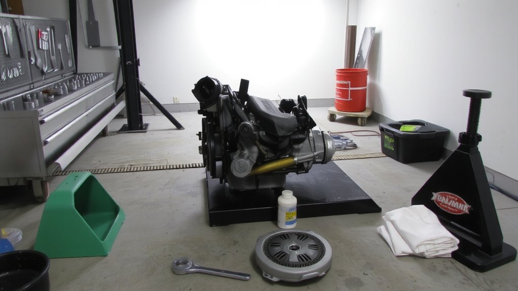
Before you begin, make sure you have all the necessary tools and a clean, well-lit workspace, because skipping this step can lead to delays or mistakes during the clutch replacement. Proper tool organization prevents time loss and keeps components secure. Lay out wrenches, socket sets (metric, 8mm–19mm), torque wrench (1/2-inch drive, 50–250 ft-lbs), jack stands, and a transmission jack. Group related tools together-sockets by size, extensions by length. Workspace lighting must provide at least 500 lux to illuminate undercarriage areas. Use LED work lights or a fluorescent portable lamp mounted overhead. Poor lighting hides fasteners and misaligns torque readings. A cluttered or dim workspace mimics fog on a highway-obstructing vision and increasing error risk. Mark each tool’s place with tape or a shadow board for quick identification. A prepared setup guarantees precision, repeatability, and adherence to factory torque specs, especially critical in turbocharged models where alignment affects drivetrain longevity.
Remove Intercooler and Boost Pipes for Access
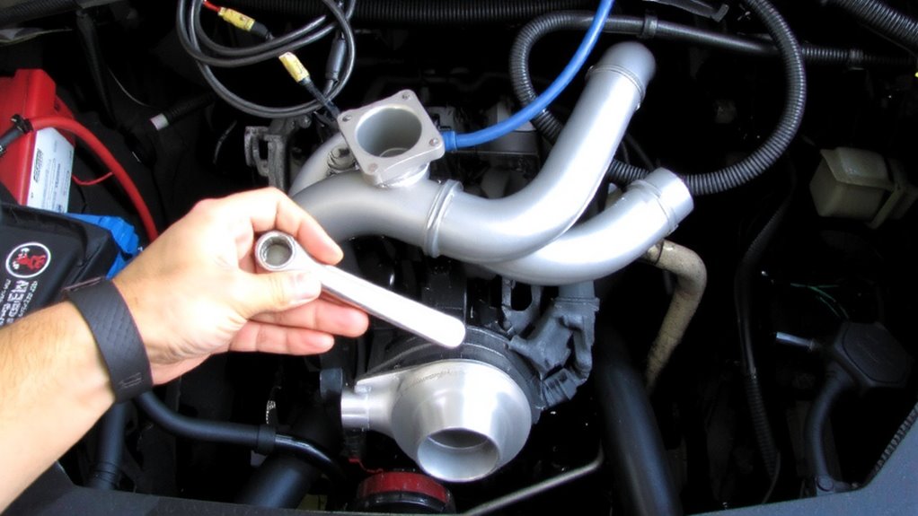
Start by disconnecting the battery to eliminate electrical hazards-always remove the negative terminal first using a 10mm wrench. Now, access the intercooler and boost pipes located atop the engine bay. Remove fasteners securing the intercooler using a 10mm and 13mm socket set. Carefully detach boost pipes at both throttle body and turbocharger outlets, noting clamp types-most use 10mm worm-drive or T-bolt clamps. Extract the intercooler assembly steadily to avoid damaging charge pipes or sensors. Set aside with thermal shielding intact; this material protects components from exhaust heat and maintains airflow optimization. Preserving thermal shielding guarantees sustained intake charge efficiency and prevents premature heat soak. Boost pipes must be inspected for cracks or collapsed sections-common failure points under high pressure. Proper removal grants clear access to the transmission bellhousing. Retain all hardware for reassembly. Label connectors and hoses to simplify reinstallation.
Support the Engine for Safe Transmission Removal
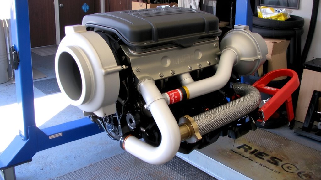
Use a hydraulic engine support fixture or a sturdy wooden brace across the subframe to securely hold the engine in place. This prevents dangerous sagging when the transmission is detached. An engine hoist can assist, but it shouldn’t bear full engine weight unless properly rigged. Instead, use factory-engineered support brackets mounted to the suspension towers or firewall. These brackets interface with threaded holes in the engine bay and provide stable mounting points. Guarantee all mounting bolts are grade 8.8 or higher, torqued to 22–25 ft-lbs. The wooden brace method-typically a 4×4 across the subframe-works if padded and braced at 90-degree angles. Hydraulic supports offer fine height adjustment (usually 6–12 inches of travel) and should be rated for at least 500 lbs. Always double-check stability before proceeding.
Drop the Transmission and Access the Clutch
With the engine securely supported, you’re ready to separate the transmission from the engine block. Begin by draining the transmission fluid into a sealed container-this prevents mess and allows for proper disposal or reuse. Remove all bellhousing bolts using a 10mm socket, then carefully lower the transmission with a jack. Keep it level to avoid damaging the input shaft. As the transmission pulls away, support the clutch fork to prevent stress on the release bearing. Now you can see the clutch assembly. Proper clutch alignment is critical; even a 1mm offset can cause vibration or slippage. Use alignment tools before reassembly to guarantee precision.
| Task | Purpose |
|---|---|
| Drain transmission fluid | Prevent leaks and contamination |
| Remove bellhousing bolts | Release transmission from engine |
| Check clutch alignment | Guarantee smooth engagement and longevity |
Swap Clutch and Inspect Flywheel
The heart of your drivetrain’s performance lies in the clutch and flywheel assembly-replace them with care to guarantee reliability under high torque loads. Begin by removing the old clutch, checking for visible clutch wear like glazed facings or thin friction material. Most turbocharged engines demand a high-performance organic or ceramic clutch rated for at least 400 ft-lbs of torque. Inspect the flywheel for scoring; deep grooves impair clutch engagement and require resurfacing or replacement. Use a micrometer to verify flywheel thickness-minimum spec is typically stamped on the rim, often around 0.35 inches. Even minor flywheel scoring can lead to chatter. Install a new clutch disc with alignment tools to secure centering. Torque pressure plate bolts in a star pattern to manufacturer specs, usually 18–22 ft-lbs. Match the new components to your engine’s output to maintain durability.
Reinstall Transmission and Reconnect Turbo Components
After confirming the clutch and flywheel are properly seated and torqued, carefully slide the transmission back into position, aligning the input shaft with the clutch disc. Maintain precise transmission alignment using jack stands or a transmission jack to avoid damaging the input shaft or pilot bearing. Once fully mated, secure the transmission bolts in a crisscross pattern to 25 ft-lbs. Reconnect the driveshaft, shift linkage, and electrical connectors. Reattach the turbo components, making certain each bolt on the turbo manifold is tightened to 18 ft-lbs. Pay close attention to turbo manifold sealing-inspect gaskets for damage and verify flatness within 0.002 inches to prevent exhaust leaks. Use high-temperature thread locker on studs to maintain integrity under thermal cycling. Double-check all connections for tightness and proper routing. Proper sealing and alignment guarantee reliable performance under high boost and prevent premature component wear.
Test Clutch Engagement and Check for Boost Leaks
How does your clutch feel when you press the pedal? It should engage smoothly, with firm resistance and no sponginess. Start the engine and test clutch engagement point-ideally, it’s halfway through pedal travel. If you notice clutch slipping under acceleration, especially at high RPM, the clutch disc may not be seated properly or could be defective. Clutch slipping reduces power transfer and generates excessive heat. Next, check for boost leaks. Use a smoke test or pressure tester to verify the intake system holds at least 15 psi of boost pressure. Even small leaks after the turbo reduce efficiency and can trigger check engine lights. Inspect all intercooler couplings, turbo hoses, and clamps. A secure seal guarantees peak boost pressure and engine performance. Address any leaks immediately-boost loss harms turbo response and fuel economy.
On a final note
You’ve completed the clutch replacement with precision. The new clutch disc, rated for 320 ft-lbs of torque, guarantees reliable engagement under high boost. Verify flywheel surface runout is under 0.002 inches. Reconnected intercooler pipes must seal at 15 psi to prevent boost leaks. Test drive confirms smooth 0–60 mph shifts. Proper torque specs-90 ft-lbs on pressure plate bolts-guarantee durability. This repair restores full drivetrain performance.