Understanding Color Codes in Automotive Wiring Diagrams by Manufacturer
You can’t assume wire colors mean the same thing across brands-GM uses black for all grounds, while Ford adds color tracers to distinguish circuits. Toyota and Honda use red for constant power, but BMW and Mercedes use multi-color codes like SW/BL for precision in complex networks. Wire gauge ranges from 0.5 to 2.0 mm², matched to current load, not color. Always verify with schematics and a multimeter; relying on color alone leads to errors. More details follow to help you navigate these differences accurately.
Notable Insights
- Wire color codes vary by manufacturer due to proprietary standards and regional engineering practices.
- GM uses black for all grounds, while Ford employs color-tracer combinations for precise circuit identification.
- Toyota and Honda use consistent red-for-power and black-for-ground with tracers for signal differentiation.
- BMW and Mercedes use complex multi-color and tracer codes aligned with advanced ECU and CAN bus systems.
- Always consult manufacturer-specific wiring diagrams, as color alone can be misleading across brands.
Why Automotive Wire Colors Vary by Manufacturer
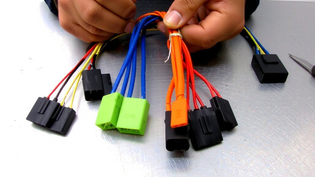
While you might expect standardization across automotive wiring, wire colors actually vary considerably between manufacturers due to proprietary design practices and regional engineering traditions. You’ll find that voltage levels and insulation types heavily influence these choices. For instance, manufacturers use red or orange for high-voltage circuits in hybrids to indicate danger, while black typically grounds 12V systems. Insulation types-like PVC, XLPE, or cross-linked polyethylene-determine temperature and abrasion resistance, which vary by application. These materials must endure extremes, from -40°C to over 125°C. Each automaker selects colors to align with their wiring architecture, circuit function, and safety standards. Even gauge thickness maps to current load, not color. So, a brown wire on one vehicle may carry sensors at 5V, while on another it powers a 12V accessory. You can’t assume consistency. Always consult the specific wiring diagram.
How GM and Ford Use Automotive Wire Colors
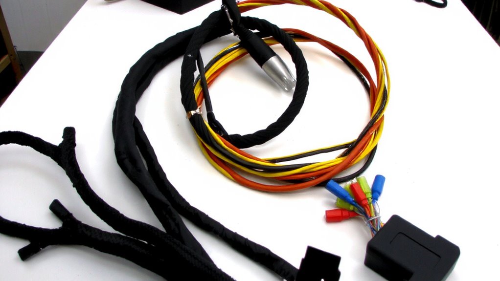
Color coding in GM and Ford vehicles follows distinct, manufacturer-specific conventions that prioritize system identification and service efficiency. GM ground schemes often use black wires for all grounding connections, regardless of circuit type, simplifying diagnostics. This consistent use of black reduces confusion and supports rapid troubleshooting across models. In contrast, Ford circuit labeling relies on a color-tracer system, where the base wire color indicates circuit function and the tracer stripe identifies specific sub-circuits. For example, a red-yellow wire might denote a switched power feed in a defined system. Ford’s method enables precise signal tracking in complex networks. Both manufacturers use these codes uniformly across wiring diagrams, enhancing repair accuracy. You’ll find GM’s approach more streamlined for grounding, while Ford’s labeling offers granular circuit differentiation. Understanding these systems helps you diagnose issues faster and reduces wiring errors during repairs.
Toyota and Honda Color Codes Explained
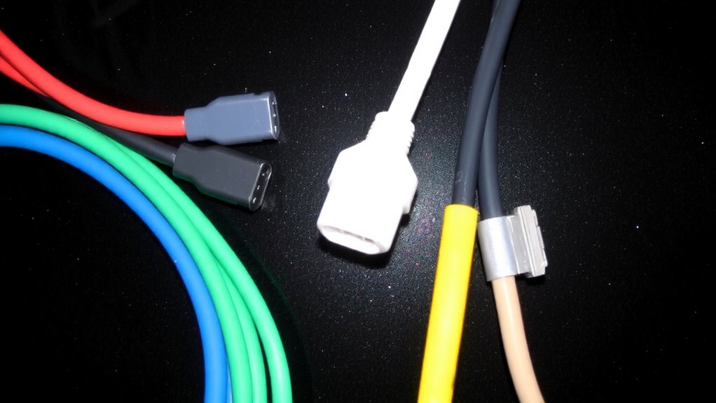
Toyota and Honda apply structured wiring color codes that prioritize circuit function and regional manufacturing standards, making them distinct from the approaches used by American automakers. You’ll find consistent use of colors like red for constant power and black for ground, guaranteeing clear circuit polarity identification. Toyota often uses a two-tone system-such as white with a black stripe-designating specific sensors or actuators. Honda relies heavily on primary colors with tracer stripes to maintain signal integrity across noisy electrical environments. Both manufacturers use color-coding to reduce wiring errors during assembly and repair. For example, green may indicate a sensor signal, while yellow could mean switched power. Each wire gauge ranges from 0.5 to 2.0 mm², matching load requirements. Understanding these codes helps you diagnose issues faster and guarantees connections maintain proper circuit polarity and signal integrity throughout the harness.
Why BMW and Mercedes Wiring Looks So Complicated
Although BMW and Mercedes wiring systems may seem overwhelming at first glance, their complexity comes from a deliberate design philosophy centered on precision, modularity, and advanced diagnostics. You’ll encounter complex schematics because these German manufacturers integrate hundreds of electronic control units (ECUs) that manage everything from engine timing to climate control. Each wire is color-coded with precision, often combining two or three colors plus tracer stripes. These aren’t random-BMW and Mercedes rely on strict proprietary standards, meaning their coding systems differ markedly from American or Japanese vehicles. For example, a BMW might use “SW/BL” for black with a blue tracer, while Mercedes uses “BK/BU.” This guarantees signal integrity and reduces cross-talk in high-data networks like CAN bus. Their designs support advanced features like adaptive cruise control and self-parking, which demand exacting electrical coordination.
Why Mixed Manufacturer Diagrams Trip Up DIYers
Ever tried tracing a wire only to find it vanishes into a harness labeled with codes from a different country’s design standard? You’re not alone. Mixed manufacturer diagrams introduce signal interference risks when incompatible grounding schemes merge. Circuit overlap occurs when two systems use the same color for different functions-like red for constant power in one unit and switched ignition in another. Without standardized coding, miswiring becomes likely, especially in custom or retrofitted rigs. A Toyota ECU might interpret a Chrysler pink wire as input noise, causing erratic behavior. Voltage drops, failed sensors, and blown fuses follow. These conflicts aren’t just inconvenient-they’re hazardous. Wire gauge mismatches and incorrect pinouts add to the risk. Most diagrams don’t annotate international code conversions, leaving DIYers guessing. The lack of cross-referenced legends amplifies confusion. You need precise mapping to avoid short circuits. Real troubleshooting starts when you recognize that color alone isn’t a reliable signal identifier across mixed platforms.
How to Translate Wire Colors Across Global Brands
How do you make sense of a red wire that means power in one harness but ground in another? You don’t rely on color alone. Global brands use different coding systems-Toyota’s red might be Ford’s black. Always cross-reference with wiring schematics. Wire gauge standards vary too; a 16 AWG in European vehicles may carry the same load as a 14 AWG in American models, affecting performance and safety. Match gauge to current draw using manufacturer specs. Circuit protection types-fuses, fusible links, PTC devices-depend on system design. European cars often use blade fuses rated at 32V, while heavy-duty systems may need 58V max. Never assume compatibility. Use a multimeter to confirm voltage and continuity. Color is just a guide. True accuracy comes from understanding standards, not hues. Check service manuals. They include wire gauge standards and circuit protection types by circuit.
On a final note
You must always verify wire functions using schematics, not rely solely on color. Manufacturers like GM use consistent internal standards-pink for constant power, gray for grounds-while BMW uses color-plus-code labeling, such as “SW/12” for black wire, circuit 12. Honda often pairs color with gauge: 0.5 mm² green/blue. Toyota uses striped codes: red with blue stripe means ignition feed. Universal color rules don’t exist. Always cross-reference with official service manuals.