How to Properly Support a Manual Transmission During Removal and Installation
Use a hydraulic transmission jack rated for at least 1,000 pounds to safely support the unit during removal and installation. Set telescoping arms between 24 and 40 inches to match your transmission’s length, locking them securely. Position the front arm near the bellhousing, the rear near the tailshaft. Guarantee swivel pads contact flat surfaces to prevent slipping. Keep the transmission level within 2 degrees of factory alignment. Lift straight up with smooth, controlled motion-never tilt or twist. A precision pump and release valve let you adjust height accurately. Balance and stability are critical when working close to drivetrain components. Proper setup prevents damage and eases reinstallation. You’ll see how alignment affects engagement as the process continues.
Notable Insights
- Use a hydraulic transmission jack rated for at least 1,000 pounds to safely support the transmission during removal and installation.
- Adjust telescoping arms to match transmission length and secure them to maintain balance and prevent shifting.
- Position the transmission jack’s swivel pad to match the transmission angle and ensure even weight distribution.
- Lift the transmission straight and steadily, maintaining clearance between the bell housing and engine block.
- Support the driveshaft after disconnecting it to prevent strain on the rear axle during transmission removal.
Choose the Right Transmission Jack
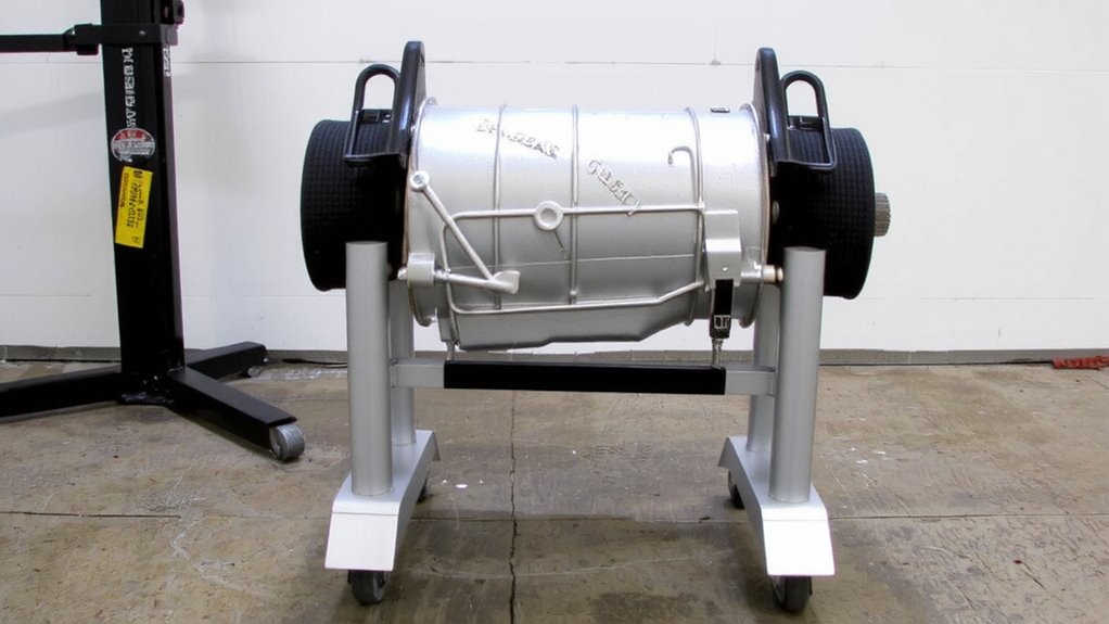
A good transmission jack makes all the difference when you’re working under your car. Choosing the right one guarantees stability, control, and safety during transmission jacking. Look for a hydraulic jack rated for at least 1,000 pounds-most manual transmissions weigh between 100 and 400 lbs, but capacity provides a critical safety margin. A model with a low minimum height of 8 inches allows access even on lowered vehicles. Telescoping arms ranging from 24 to 40 inches accommodate various transmission lengths. Prioritize units with swivel pads to match transmission angles. Always follow safety precautions: use jack stands on the vehicle frame, never rely solely on the transmission jack, and secure the load with straps. Precision engineering in the jack’s pump and release valve guarantees smooth height adjustments. The right jack combines durability, reach, and control for reliable performance.
Set the Adjustable Arms to Balance the Transmission
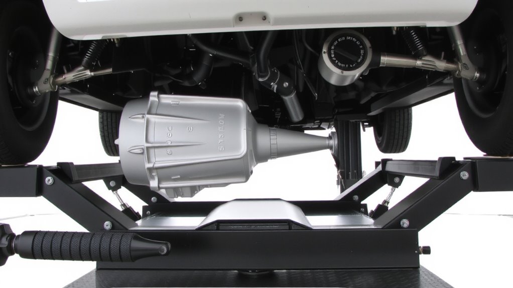
Once you’ve secured the transmission on the jack, adjust the arms to evenly support its weight and prevent tipping. Proper weight distribution is critical-uneven support can strain the casing or damage internal components. Extend the adjustable arms to match the transmission’s length, typically between 24 and 36 inches, depending on model. Position the front arm near the bellhousing and the rear arm close to the tailshaft for ideal gear balance. Tighten the locking mechanisms to secure each arm in place, ensuring no lateral or vertical movement. The transmission should remain level, with a tolerance of no more than 2 degrees of tilt. This alignment mimics its mounted position in the vehicle, minimizing stress. Correct arm placement also improves control during removal and installation, reducing risk of injury. Always double-check all connections before proceeding.
Disconnect the Driveshaft and Shift Linkage
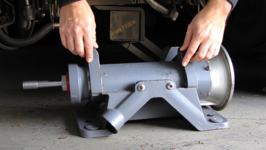
Before you begin detaching any components, make sure the vehicle is securely raised and supported on jack stands, because safety’s non-negotiable when working under a lifted car. Start with driveshaft removal by loosening the bolts connecting the driveshaft to the rear differential and transmission output shaft. Use a wrench to mark alignment before removal-this guarantees balanced reinstallation. Support the driveshaft with a strap or hoist to prevent strain on the rear axle. Next, perform shift linkage detachment by locating the linkage rods at the transmission tail. Remove the cotter pins and clevis pins carefully using pliers and a punch. Most linkages use 10mm or 12mm hardware; keep fasteners labeled. Disconnect all connections fully so the transmission shifts freely during extraction. Complete both steps before moving on-partial disassembly creates risk during removal.
Lift the Transmission Straight and Steady
With the driveshaft and shift linkage fully removed, you’re ready to free the transmission from engine alignment. Lift the transmission straight and steady to avoid misalignment or damage. Any lateral force can disrupt transmission alignment, stressing mounts and input shaft components. Support the unit with a transmission jack, adjusting height incrementally. Keep the lift path perpendicular to the ground-this maintains balance and counters engine torque effects from suspension movement. Maintain at least 1/8-inch clearance between the bell housing and engine block throughout removal. Uneven lifting introduces binding, risking pilot bearing damage or warped mating surfaces. The transmission weighs 120–150 lbs, so controlled motion is essential. Never pivot or tilt the unit while detached. Engine torque during vehicle movement can shift weight across axles, altering undercarriage geometry. Steady, vertical force preserves component integrity and guarantees simple reinstallation later.
Align the Input Shaft Before Seating
Though the transmission is nearly in place, proper input shaft alignment is critical before you attempt final seating. Input alignment guarantees the splines on the clutch disc and transmission input shaft engage smoothly. Misaligned shaft positioning can damage the clutch, pilot bearing, or throw-out bearing. Begin by visually confirming the transmission’s input shaft is parallel to the crankshaft centerline. Gently push the transmission forward while guiding it into position. You should feel the input shaft slide in without resistance. If you meet resistance, pull back and recheck shaft positioning. Never force the transmission into place-doing so risks internal damage. Use alignment tools or a pilot shaft to verify input alignment before installation. Proper shaft positioning allows the transmission to seat fully against the engine block, guaranteeing correct clutch engagement and drivetrain function.
Secure the Transmission Before Releasing the Jack
After the transmission slides fully into place, immediately secure it before removing the transmission jack. Proper bolt engagement guarantees transmission stability and prevents misalignment. Use the manufacturer-specified bellhousing bolts-typically M10 x 1.5mm, torqued to 25–30 ft-lbs-in a crisscross pattern. Begin with at least two bolts diagonally opposite each other to evenly distribute clamping force. These fasteners bear structural load and eliminate movement during jack removal. Maintaining jack safety means never relying solely on temporary supports. Gradually lower the jack while monitoring for binding or stress. Confirm the transmission rests fully on the engine block without gaps. Only after all mounting points are secured should you fully remove the jack. Doing so reduces risk of injury and damage. Final alignment depends on precise initial support. Always double-check bolt tightness before proceeding.
On a final note
You must support the transmission properly to avoid damage. Always use a rated transmission jack capable of handling at least 600 lbs. Adjustable arms distribute weight evenly across the casing. Lift straight to align the input shaft with the pilot bearing-misalignment causes damage. Confirm the flywheel and clutch contact evenly before bolting. Never release the jack until all mounting bolts are torqued to spec-typically 25–30 ft-lbs. Safety and precision guarantee reliable operation.