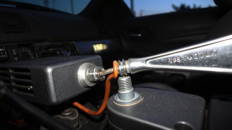
How to Use a Noid Light to Test Fuel Injector Pulse Signal
You test a fuel injector’s pulse signal by plugging a noid light into the injector’s harness connector, replacing the injector’s plug. The LED flashes when the ECU sends a voltage pulse, confirming electrical signal activity. Use a 12V-compatible noid light and ground the black lead properly. A steady blink means normal operation; no flash indicates a break in power, ground, or ECU control-check fuses, relays, and wiring next. Further verification steps follow.
Notable Insights
- Turn off the ignition and disconnect the battery to ensure safety before connecting the noid light.
- Select the correct noid light for your vehicle and plug it into the fuel injector harness socket.
- Ground the noid light’s black wire to the battery negative or clean metal chassis for proper circuit operation.
- Crank the engine while observing the noid light; a steady flash indicates a proper injector pulse signal.
- No flashing suggests issues in wiring, fuses, relays, or ECU that require further electrical testing.
What a Noid Light Is and Why It’s Useful
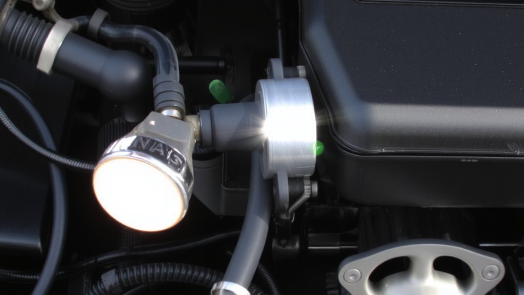
A noid light is a simple diagnostic tool mechanics use to test fuel injector operation. You connect it to the injector’s electrical connector to see if the engine’s computer sends a pulse signal. Without that pulse, the injector won’t spray fuel, and your engine won’t run properly. The noid light flashes when it detects voltage, confirming the signal is present. This test doesn’t check fuel pressure or ignition timing, but those systems must work for the engine to start. If the injectors pulse but the engine still won’t run, fuel pressure or ignition timing could be off. Low fuel pressure prevents proper atomization, while improper ignition timing causes misfires. The noid light helps isolate electrical faults from mechanical ones. It’s cheap, reusable, and works across many vehicle makes. You’ll save time and avoid unnecessary part replacements.
How Noid Lights Detect Injector Pulse Signals
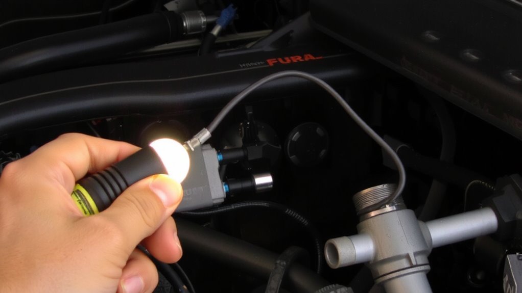
You’ve seen how a noid light identifies whether the engine’s computer sends a signal to the fuel injectors, but now it’s time to understand how it actually detects that pulse. The noid light plugs into the injector’s harness, replacing the injector connector. When the engine runs, the computer sends a pulsed voltage signal to the injector. The noid light uses internal electrical resistance to safely simulate the injector’s load, preventing damage to the engine’s control module. As the signal activates, an LED in the noid light flashes. Each flash corresponds to a pulse, visually confirming signal frequency. The rapid blinking reflects the duty cycle and timing controlled by the ECU. You can observe consistent or erratic flashing patterns, indicating proper or faulty signal delivery. Unlike test lights for constant voltage, noid lights are designed specifically to respond to the pulsed nature of injector circuits. This precision makes them reliable for diagnosing signal issues.
Gather Tools and Safety Tips Before Testing
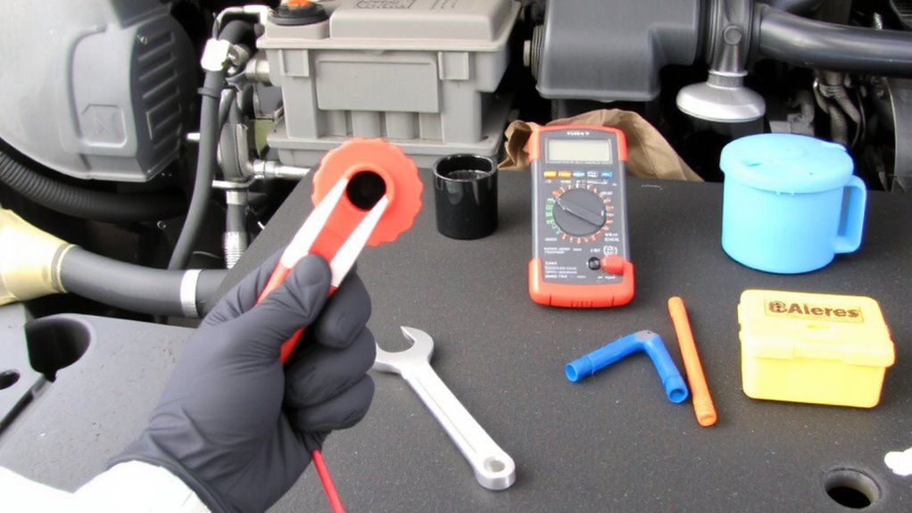
Before grabbing your tools, make sure the vehicle is in a safe state for testing. Turn off the ignition and disconnect the battery to guarantee electrical safety during preparation. You’ll need a compatible noid light set, insulated gloves, and safety glasses. Verify your vehicle’s fuel injector harness voltage-most systems operate at 12V DC. Always confirm proper grounding by attaching the noid light’s black lead directly to the battery’s negative terminal or a clean, unpainted metal surface on the chassis. Poor grounding causes false readings and risks damaging sensitive engine control modules. Use only test leads rated for automotive diagnostics, typically with 600V insulation. Keep loose clothing and hair clear of moving parts. Work in a dry, well-lit area to minimize hazards. Double-check tool condition-frayed wires or cracked probes compromise both accuracy and safety. Preparation guarantees reliable results.
How to Connect the Noid Light to an Injector
With safety measures in place and your tools verified, you’re ready to link the noid light to the injector circuit. First, locate the fuel injector using the engine’s injector placement diagram-this guarantees you access the correct connector. Disconnect the injector’s electrical plug from the harness, then plug the noid indicate into the harness socket, not the injector itself. This allows the noid light to receive the pulse signal without power interruption. Proper seating of the noid light’s pins prevents poor contact and signal interference. Avoid routing the test cord near spark plug wires or alternators to minimize electrical noise. The noid light is designed to work on 12-volt systems and mimics injector impedance. Secure the light where you can clearly see it during cranking. Correct connection guarantees an accurate reading for the next step: interpreting the flash pattern.
What the Noid Light’s Flashing Pattern Means
A consistent flashing pattern reveals the health of the fuel injector’s electrical signal. Each blink corresponds to an energizing injector, and irregularities may indicate control issues. You should observe a steady, rhythmic flash at idle-typically once per engine revolution in sequential systems. The table below outlines common patterns and what they mean:
| Pattern | Interpretation | Possible Cause |
|---|---|---|
| Steady flash | Normal operation | Healthy ECU signal |
| Flickering | Signal distortion | Wiring damage or loose harness |
| Slow or delayed | Injector delay | Clogged injector or weak pulse |
Signal distortion disrupts timing, reducing fuel accuracy. Injector delay affects air/fuel ratio and combustion efficiency. A noid light won’t measure voltage amplitude, but it does expose timing flaws. Use it alongside other diagnostics to confirm signal integrity. Always compare observed behavior to manufacturer specs.
No Pulse? Check These Common Issues
You’ve checked the flashing pattern and seen nothing-no blink, no flicker, just silence from the noid light. This usually means the injector isn’t receiving a pulse signal. Start by checking the basics: a weak battery can prevent the ECU from sending proper signals. Verify voltage at the battery is at least 12.6V with the engine off. Low voltage disrupts communication, mimicking a dead system. Next, inspect for faulty wiring between the injector harness and ECU. Look for frayed, corroded, or disconnected wires. Test continuity using a multimeter; resistance should be less than 0.5 ohms across wiring segments. Open circuits or high resistance break the signal path. Damaged connectors or pin corrosion are common culprits. Don’t overlook grounds-poor grounding interrupts control signals. Always verify power and ground circuits before diving deeper. These steps isolate electrical faults efficiently.
Test the Relay, Fuses, and ECU Next
If the noid light still shows no pulse after checking power, grounds, and wiring, it’s time to examine the relay, fuses, and ECU. Start by verifying fuse integrity-use a multimeter to test for continuity. A blown fuse interrupts power delivery and must be replaced with one of the same amperage rating, typically 10 to 15 amps. Next, assess relay function. With the ignition on, listen for a click when activating the circuit. Lack of response suggests a failed relay. Test the relay socket: terminals 85 and 86 should receive 12V, while 87 and 30 connect when energized. If both fuses and relays check out, the issue may lie in the ECU. The ECU sends the switching signal to the injectors. Loss of this signal often points to internal ECU faults or disabled driver circuits. Always confirm power and ground at the ECU connector before concluding failure.
On a final note
You now have a reliable method to verify injector pulse signals. A noid light plugs directly into the fuel injector connector, drawing power from the vehicle’s ECU pulse. The LED flashes when the injector signal is present. Each flash corresponds to an actuation command, typically at 12V. Absence of flash indicates a break in signal, possibly due to faulty relays, blown fuses, or ECU issues. This simple tool delivers critical diagnostic insight.