How to Identify Shared Circuits in a Vehicle’s Electrical System
You can spot shared circuits by noticing if multiple systems-like headlights and power windows-fail together or flicker under load. Check your fuse box diagram for labels like “Radio/Interior Lights” on one fuse. Test fuses with a test light while the ignition is on. Use a multimeter to compare voltages-similar readings suggest shared power. Confirm with continuity tests (key off, fuses out) between circuits. Trace wires to map connections and isolate shared paths. Next, you’ll see how to fix and separate them for reliable performance.
Notable Insights
- Check for multiple unrelated components failing simultaneously, as this often indicates shared circuits with common power or ground issues.
- Consult the fuse box diagram to identify fuses labeled for multiple systems, which reveals intentionally shared circuits.
- Use a test light to verify power at both ends of a fuse, confirming circuit activity and potential sharing when multiple systems lose power together.
- Measure voltage at suspected circuits with a multimeter; nearly identical readings suggest they share the same power source.
- Trace wiring with a multimeter in continuity mode to find unexpected connections between circuits, confirming shared paths beyond fuse labels.
Check for Symptoms of Shared Circuits
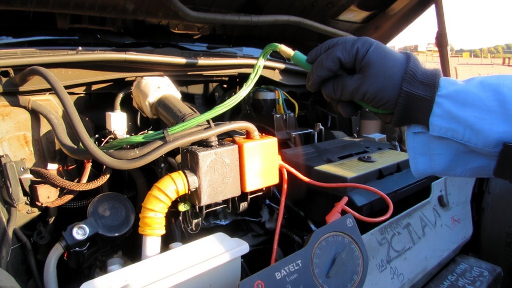
Why might multiple electrical components fail at once? You’re likely dealing with shared circuits. When unrelated devices-like headlights and power windows-draw power from the same circuit, flickering lights can occur under load. Intermittent failures are common if the shared wiring is degraded or overloaded. A voltage drop below 11.5V during operation indicates circuit strain. Devices may reset or dim, especially when high-amperage accessories activate. Shared circuits often lack dedicated fuses, increasing cross-component interference. Check for synchronized malfunctions-e.g., radio cuts out when AC engages. Resistance above 5 ohms in a ground wire suggests poor connections, worsening shared load issues. Use a multimeter to monitor voltage stability across components while switching systems on and off. If multiple systems dip in voltage simultaneously, they’re likely sharing a circuit. Observe amperage draw; circuits exceeding 80% of fuse rating (e.g., >12.8A on a 16A fuse) risk overheating. These signs point to circuit sharing. A reliable car multimeter is essential for accurately diagnosing these electrical issues.
Read Your Fuse Box Diagram
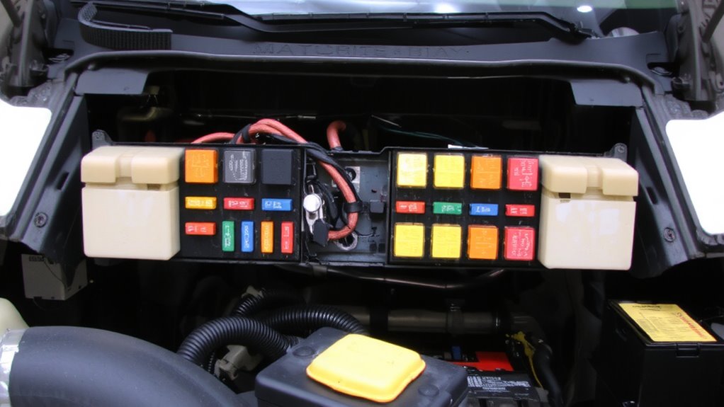
Although you might be tempted to start probing wires with a multimeter right away, take a moment to consult your vehicle’s fuse box diagram first-it’s the fastest way to spot shared circuits. Accurate fuse identification begins here. The diagram, usually printed on the fuse box cover or in the service manual, maps each fuse’s location, amperage rating, and circuit function. Diagram interpretation helps you see which components share a fuse, indicating a shared circuit. For example, a 15-amp fuse labeled “Radio/Interior Lights” powers both systems, linking them electrically. Modern vehicles often group low-draw accessories on shared fuses to reduce wiring complexity. Misinterpreting the diagram can lead to misdiagnoses, so verify fuse numbers and symbols carefully. Recognizing these relationships early streamlines troubleshooting. You’ll avoid unnecessary tests and focus on confirmed circuit overlaps. Always cross-reference the diagram with your vehicle’s make, model, and year-designs differ greatly.
Test Fuses With a Test Light
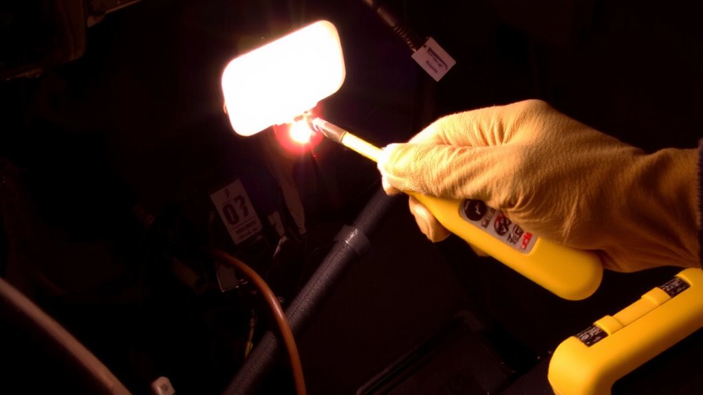
Now that you’ve reviewed the fuse box diagram and identified potential shared circuits, it’s time to verify those findings physically. Begin with a thorough fuse inspection using a test light. Connect the test light’s alligator clip to a known good ground. Turn the ignition to the “on” position without starting the engine. Probe each fuse’s test points-one side at a time. If the test light illuminates on both sides, the fuse is intact and receiving power. No light means a blown fuse or no circuit power. Test light usage confirms live circuits quickly and reliably. A standard 12V test light works for most vehicles. Check fuses related to suspected shared circuits first. This step guarantees only active circuits are considered. It eliminates guesswork. Accurate test light usage reduces diagnostic time. It’s a simple, effective method to verify circuit activity before further testing. For reliable results, choose a best automotive test light that offers durability and clear visibility.
Use a Multimeter to Confirm Shared Circuits
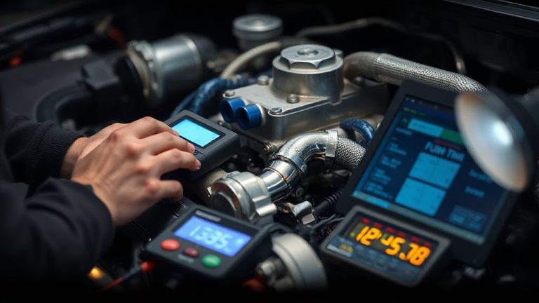
How can you be certain two circuits are truly sharing a power source? Use a multimeter to measure voltage at both circuits while powered. If readings are nearly identical, they likely share a supply. A significant voltage drop in one suggests separate sources or high resistance. Set your multimeter to DC voltage, place the red probe on the power side of each circuit, and the black to chassis ground. Compare results. Then, perform a continuity check between the circuits’ positive leads-with the system off and fuses removed. No continuity means separate circuits. Continuity indicates a direct connection, confirming shared wiring. Always make sure the vehicle key is off during continuity tests to prevent false readings. This method delivers precise validation using measurable data, not guesswork. Accurate diagnostics depend on these steps, ensuring you avoid misidentifying unrelated circuits as shared.
Follow Wires to Find Shared Systems
Tracing wires is the most reliable way to confirm shared systems in a vehicle’s electrical network. You’ll need a wiring diagram specific to your make and model-this is essential for accurate circuit mapping. Begin wire tracing from the fuse box, following each circuit with a multimeter in continuity mode. Connect the probes to the fuse terminals and corresponding component connectors. If continuity exists along unexpected paths, those circuits are shared. Use colored tape to label wires and create your own circuit mapping diagram. Most modern vehicles share circuits between interior lights, radios, and power accessories. Trace at least 80% of each wire’s path to avoid routing errors behind junction blocks or under trim panels. Don’t rely solely on color-wires often change color after splices. Proper wire tracing reveals hidden connections that multimeter tests alone can miss.
Fix and Isolate Shared Circuit Issues
Once you’ve mapped the shared circuits, you can begin isolating faults by disconnecting power and separating overlapping systems. Use circuit tracing to pinpoint where wires merge or draw from the same fuse. This helps identify unintended loads. Perform voltage analysis at each junction block and connector under load to detect voltage drops exceeding 0.2V, which indicate resistance or overloading. You should test each circuit segment with a digital multimeter set to DC volts. Compare readings to the vehicle’s service manual specs-deviations over 5% suggest a problem. Isolate components one at a time, checking for parasitic draws above 50mA. Re-route shared wires when necessary, using OEM-specified gauge wire. Install separate fuses for high-draw accessories. Reliable circuit tracing and consistent voltage analysis mean faster diagnosis. You’ll reduce electrical noise, prevent overheating, and eliminate intermittent failures caused by shared circuit overload.
On a final note
You now know how to identify shared circuits in a vehicle’s electrical system. Start by checking for flickering lights or intermittent failures, which suggest circuit overlap. Refer to the fuse box diagram-usually rated for 12V DC systems-to trace shared connections. Use a test light or multimeter, accurate to ±0.1V, to verify voltage drops. Follow wiring paths; circuits sharing a ground or power source often share loads. Isolate issues by disconnecting components.