How to Replace an Internal Regulator in a Vintage Car Alternator
You’ll need to disconnect the battery and remove the alternator to access the internal regulator. Look for signs like flickering headlights or voltage readings outside 13.5–14.5 volts. Open the case by removing the housing bolts, then locate the regulator near the brushes. Replace it with a 12V, 50–60 amp solid-state unit matching your model. Reassemble carefully, reinstall, and test output at idle and 2,000 RPM. A stable 13.8–14.7 volt reading confirms correct operation. Further verification steps guarantee long-term reliability.
Notable Insights
- Disconnect the battery and remove the alternator from the vintage car to safely access the internal components.
- Open the alternator case by removing mounting bolts and carefully separating the front and rear housing halves.
- Locate the internal regulator near the brush assembly, then unplug wiring and remove its mounting screws.
- Install a compatible 12V solid-state regulator with matching terminal layout and secure it with proper torque.
- Reassemble the alternator, reinstall it, and test charging voltage to ensure it reads 13.8–14.7 volts at idle.
Signs Your Vintage Car’s Regulator Is Failing
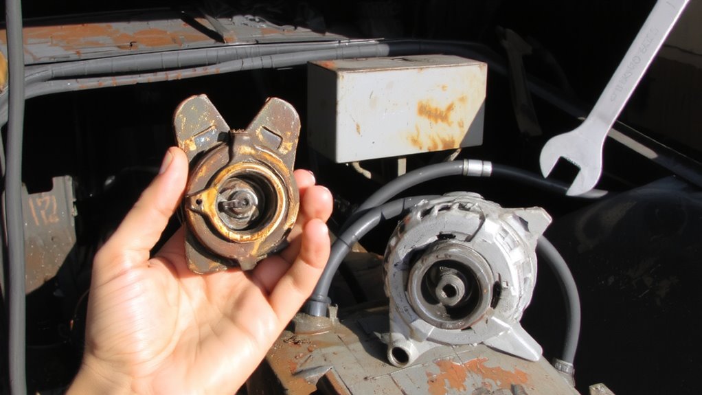
Why is your vintage car’s electrical system acting up? A failing internal regulator often causes electrical fluctuations, disrupting voltage output. You may notice dim or flickering headlights, especially at idle. The charging system should maintain 13.5 to 14.5 volts; readings outside this range indicate regulator issues. Persistent overcharging or undercharging damages the battery and other electronics. Overheating components, such as a hot alternator case or burnt wiring near the regulator, are red flags. Excessive heat degrades internal connections and solder joints. Voltage spikes above 15 volts stress sensitive components. Conversely, output below 13 volts prevents proper battery charging. The regulator manages field current to control alternator output. When it fails, that control weakens or stops. These symptoms point to an aging or faulty internal regulator needing replacement. Early diagnosis prevents collateral damage. Monitor your system with a digital multimeter for accuracy.
Gather Tools and Parts for Regulator Replacement
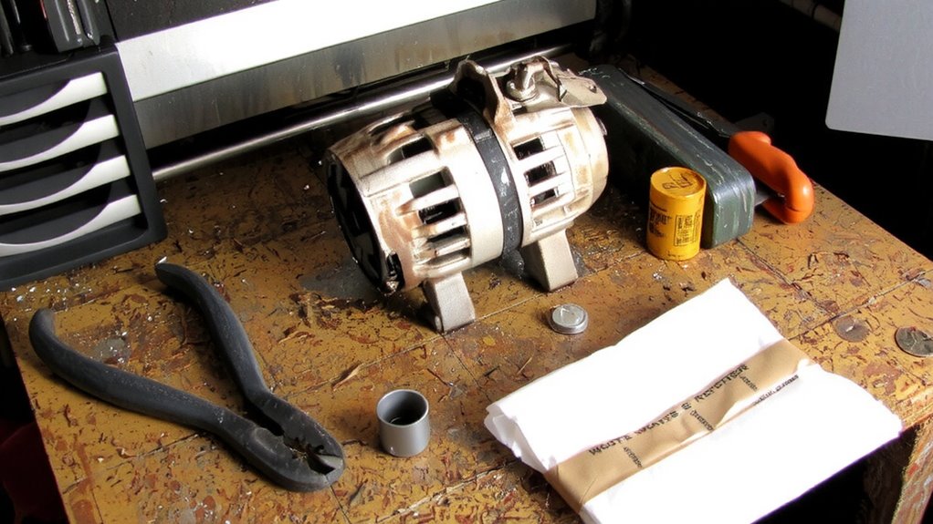
Before diving into the alternator, make sure you have the right tools and components on hand to avoid delays and guarantee a clean repair. Begin with safety precautions: disconnect the battery and wear insulated gloves and safety glasses. Prepare your workspace setup with a clean, well-lit bench and anti-static mat to protect sensitive parts. You’ll need a full set of metric wrenches, a screwdriver set, and a precision multimeter. Obtain a replacement internal regulator matched to your alternator model-typically a 12V, 50–60 amp unit for vintage vehicles. Include dielectric grease and heat-shrink tubing for secure connections. Keep original mounting hardware in a labeled tray. Verify fitment using your alternator’s OEM specifications. Having everything ready streamlines the process and reduces error risk. A comfortable and mobile work surface can enhance efficiency, so consider using a best automotive creeper for easy access under the vehicle when removing or reinstalling the alternator.
Remove the Alternator From Your Vintage Car

Now that your tools and replacement regulator are ready, it’s time to focus on removing the alternator from your vintage car. Begin by disconnecting the battery to prevent electrical shorts. Then, label and disconnect all alternator wiring carefully to guarantee correct reassembly. Use a socket set to loosen the mounting bolts and remove the drive belt. Pulley removal is often required before full alternator extraction-use a puller tool to avoid damaging the shaft.
| Step | Action |
|---|---|
| 1 | Disconnect battery and alternator wiring |
| 2 | Remove drive belt and loosen mounting bolts |
| 3 | Perform pulley removal using a puller |
Handle the unit gently-internal components are sensitive. Once free, set the alternator on a clean, dry workspace for the next phase.
Open the Alternator Case to Access the Regulator
With the alternator safely removed and placed on a clean workbench, your next step is to open the case to reach the internal regulator. Most vintage alternators use a two-piece aluminum housing marked with case labeling indicating alignment and internal components. Carefully inspect the seam between the front and rear housings to identify the fastener locations. Use a socket or wrench to loosen the screws securing the halves-many models use 8mm or 5/16″ bolts with a coarse screw thread type common in automotive electrical components. Remove each screw slowly, keeping track of placement, as lengths often vary. Once all fasteners are out, gently separate the halves by hand, avoiding prying that could damage internal connections. Take note of any internal grounding straps or wires attached near the split line. Ensuring correct reassembly later depends on observing how the case halves fit and align precisely.
Replace the Internal Voltage Regulator
Once you’ve exposed the internals, locate the voltage regulator-it’s usually a small, rectangular black or metal module mounted near the brush assembly, secured with two or three small screws. Carefully disconnect the wires, noting their positions for correct reconnection. Remove the mounting screws and pull the regulator free. Internal regulators in vintage alternators often fail due to heat degradation and electrical interference from unshielded wiring. Replace it with a modern solid-state unit rated for 12 volts and 40–60 amps, depending on your alternator model. These newer regulators resist heat degradation better and include built-in filters to minimize electrical interference. Make certain the replacement has identical mounting points and terminal configurations. Double-check wire routing to prevent contact with moving parts. Proper fitment ensures stable voltage output, typically maintaining 13.8–14.4 volts under load, critical for charging system reliability.
Reassemble and Reinstall the Alternator
After confirming all electrical connections are secure and properly insulated, begin reassembling the alternator in the reverse order of disassembly. Reattach the rear cover and stator leads carefully, making certain no pinching or abrasion occurs. Use the manufacturer’s specified torque specifications-typically 8–12 ft-lbs-for mounting bolts; under-torquing risks vibration damage, while over-torquing can crack the housing. Once fully reassembled, reinstall the alternator onto the engine bracket, securing it firmly. Reinstall the drive belt and adjust to proper belt tension-usually 1/4 to 1/2 inch deflection under 20 pounds of pressure. Correct belt tension prevents slippage and premature wear. Misalignment or incorrect tension leads to noisy operation and reduced charging efficiency. Verify pulley alignment visually or with a straightedge tool. Keep fasteners tight and inspect periodically. Reassembly done right guarantees long-term reliability and peak electrical output.
Test the Charging System After Installation
How do you know the alternator’s doing its job? Start the engine and let it idle. Use a digital multimeter to check the battery voltage. A reading between 13.8 and 14.7 volts confirms proper charging performance. If voltage is below 13.5, the alternator isn’t producing enough current. If it exceeds 15 volts, overcharging may damage electrical components. Note any fluctuations-steady voltage guarantees electrical stability. Increase engine RPM to 2,000. Voltage should remain within the same range, not fluctuating more than 0.2 volts. This consistency shows the new regulator maintains output under load. Inspect all connections for heat or corrosion. Any sign of arcing or melted insulation indicates poor electrical stability. Verify accessory function-radio, lights, wipers. Their smooth operation reflects reliable charging performance. Proper testing confirms system integrity. For accurate results, use a best car multimeter with high precision and durability.
On a final note
You’ve successfully replaced the internal regulator. This upgrade restores precise voltage control, maintaining output at 13.8–14.4 volts. The alternator now efficiently charges your 12-volt system. Proper reassembly prevents grounding issues. Belt tension should be ½ inch deflection under 10 lbs pressure. Verify with a digital multimeter. Reliable regulation prevents battery overcharge or undercharge. Your vintage car’s electrical system operates within OEM specifications, ensuring long-term performance.