How to Test Ignition Module Function in Distributor Systems
You can test your ignition module by measuring resistance and voltage at its terminals with a multimeter. First, disconnect the wiring harness and set your meter to resistance mode. A healthy module shows 5–20 kΩ. Then, check for a 3–5 V AC signal during cranking. Clean, consistent waveform peaks confirm proper function. Weak or erratic signals mean failure, even if resistance is normal. Accurate results guide your next diagnostic step.
Notable Insights
- Locate the ignition module inside or near the distributor and disconnect the wiring harness to access terminals.
- Use a digital multimeter set to resistance or DC voltage to test according to the service manual specifications.
- Measure resistance between ignition coil terminals; a reading of 5–20 kΩ indicates a sound internal circuit.
- Crank the engine and check for an AC signal voltage of 3–5 V from the pickup coil to the module.
- Observe waveform pattern with a multimeter or oscilloscope; clean, repeating peaks confirm proper ignition timing function.
What Is an Ignition Module and How Does It Work?
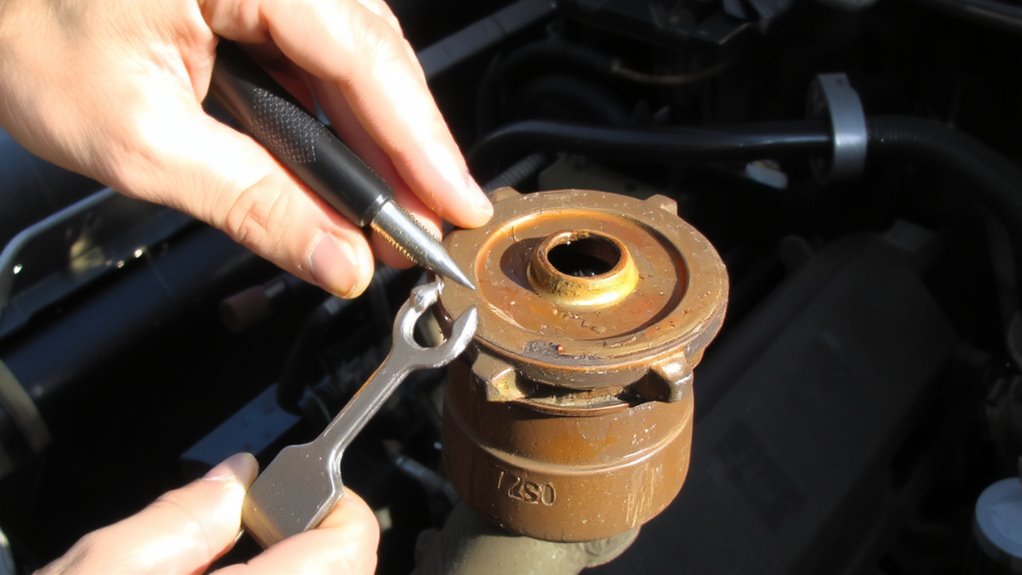
An ignition module is the brain behind your vehicle’s spark delivery system. It controls ignition timing and guarantees accurate spark generation for maximum engine performance. You rely on it to switch the ignition coil’s primary circuit on and off rapidly. This interruption creates the high-voltage surge needed for spark plug firing. The module uses input from the distributor’s pickup coil or crankshaft sensor-typically a 5- to 12-volt AC signal-to determine when to trigger the spark. Modern modules maintain ignition timing within ±2 degrees of specification across RPM ranges up to 6,000. They handle cycle rates exceeding 300 times per minute at idle, increasing exponentially with engine speed. Constructed with heat-resistant semiconductors, they manage currents of 3 to 5 amps. Without accurate spark generation, fuel combustion becomes inefficient, reducing power and fuel economy. Upgrading to high-quality Best Ignition Coils can significantly improve spark consistency and overall engine reliability.
Common Signs of a Failing Ignition Module
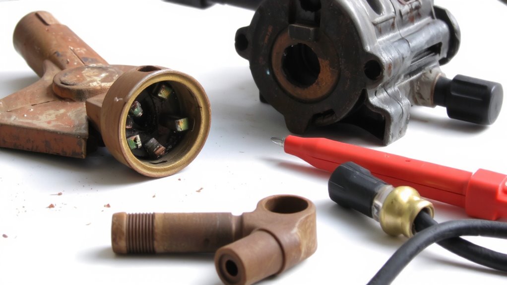
You can’t ignore the symptoms when your engine starts acting up, and a failing ignition module often lies at the heart of intermittent or severe performance issues. Engine misfires occur when the module fails to send timely voltage to the spark plugs, disrupting combustion. You’ll notice hesitation, rough idling, or jerking under load. Power loss follows as unburned fuel accumulates, reducing efficiency and torque output. The engine may crank but stall under acceleration due to inconsistent spark timing. In distributor systems, the ignition module controls dwell and spark duration-typically 2–4 milliseconds-based on signals from the pickup coil. Voltage output drops below 300 volts in faulty units, insufficient for proper ignition. These failures happen more often when the engine heats up, indicating thermal breakdown. Ignition modules operate within 5–12 volts; deviations outside this range impair function. Early detection prevents coil and plug damage.
What You’ll Need to Test the Ignition Module
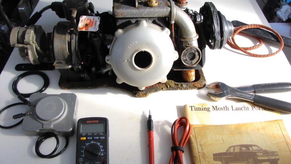
Reliability hinges on having the right tools when diagnosing ignition system faults. Proper test preparation ensures accurate readings and prevents damage to components. Always observe safety precautions-disconnect the battery before starting and wear insulated gloves. Use a clean, dry workspace to reduce electrical hazards. Below are essential items for testing:
| Tool/Item | Purpose |
|---|---|
| Digital multimeter | Measure voltage, resistance, and continuity |
| Socket wrench set | Remove distributor cap and mounting bolts |
| Insulated wire pliers | Handle spark plug wires safely |
| Safety goggles | Protect eyes from debris and sparks |
| Owner’s manual | Reference wiring diagrams and specs |
Ensure all tools are rated for automotive use. A multimeter with at least 20V DC range and 200kΩ resistance range is ideal. Keep leads undamaged and probes clean.
How to Test the Ignition Module With a Multimeter
Start by locating the ignition module, typically mounted inside or near the distributor on older vehicles or on the firewall or engine bay in newer models. Disconnect the wiring harness to access the module’s terminals. Set your multimeter to measure resistance or DC voltage, depending on the test specified in your service manual. Probe the terminals labeled for the ignition coil-usually marked “+” and “-“. A proper reading should show continuity or voltage within the manufacturer’s specs, often between 0.5 and 12 ohms or 5–8 volts, respectively. Faulty modules disrupt ignition timing and weaken spark intensity, leading to misfires or hard starts. Make certain the engine is off and the key is in the “on” position when testing live circuits. Verify ground connections are clean and tight, as poor grounding skews results. Accurate measurements here directly reflect the module’s ability to regulate spark output.
What Your Multimeter Readings Mean
A correct multimeter reading gives a clear snapshot of your ignition module’s operational state. You measure electrical resistance to check internal circuit integrity-readings outside 5–20 kΩ suggest damage. A stable signal waveform indicates proper triggering; distortion or absence means malfunction. Use AC voltage mode to observe the signal output while cranking. A healthy module produces a consistent, sharp waveform peaking between 3–5 volts. Choosing the right tool for accurate diagnostics is crucial, and a reliable car multimeter can make all the difference in detecting subtle electrical faults.
| Reading Type | Normal Value | What It Means |
|---|---|---|
| Electrical Resistance | 5–20 kΩ | Module’s internal circuit is sound |
| Signal Voltage (AC) | 3–5 V during crank | Proper signal generation |
| Waveform Pattern | Clean, repeating peaks | Reliable ignition timing |
Abnormal resistance or a weak signal waveform means the module isn’t switching correctly. You must interpret both values together-good resistance with poor waveform still indicates failure. These readings guide your diagnosis with factual precision.
What to Do If the Ignition Module Is Bad
Why is your engine misfiring or failing to start even after confirming proper voltage and resistance? Because the ignition module is likely faulty. A defective module disrupts spark timing, preventing combustion. During distributor system diagnosis, if all electrical values check out but the engine still won’t fire, suspect the module. Ignition module replacement is the next logical step. Remove the distributor cap and inspect for carbon tracking or burnt components. Most modules operate between 5–12 volts; values outside this range indicate failure. Replacement modules must match OEM specifications-check resistance ratings and pin configurations. After installing a new module, retest the system with a multimeter. Confirm spark output using a timing light or spark tester. Proper installation guarantees precise ignition timing. A successful replacement restores full engine performance. Always verify results to complete distributor system diagnosis.
On a final note
You now know how to test an ignition module in distributor-based systems. Use a digital multimeter set to ohms to check resistance between terminals, typically 0.5 to 2.0 ohms for primary windings. Confirm voltage supply at the module connector-12V with key on. No spark or fluctuating readings mean failure. Replace the module if specs fall outside manufacturer tolerances. Proper diagnostics save time and prevent misfiring.