Testing Instrument Cluster Charging Light Driver Circuit
You test the charging light driver circuit by measuring voltage at the LED driver pin with the ignition on-expect 0.1–0.3V when the light is on, rising to 13.5–14.8V when the engine starts. Use a digital multimeter with at least 1.0% accuracy and verify ground continuity to chassis, which should be under 1 ohm. A faulty ground or driver failure causes false warnings. Check for noise interference or sensor faults if voltages seem erratic. Understanding these signals reveals whether the issue lies in the circuit or cluster control.
Notable Insights
- Use a digital multimeter to measure signal voltage at the cluster’s LED driver pin with ignition on.
- Confirm charging light operates when voltage reads 0.1–0.3V and turns off when engine reaches 13.5–14.8V.
- Test ground continuity from driver ground pin to chassis; resistance should be less than 1 ohm.
- Disconnect battery before probing cluster circuitry to avoid damage and ensure accurate readings.
- Diagnose false warnings by checking for electrical noise, sensor faults, or corroded connections in the driver circuit.
How the Charging Light Circuit Works
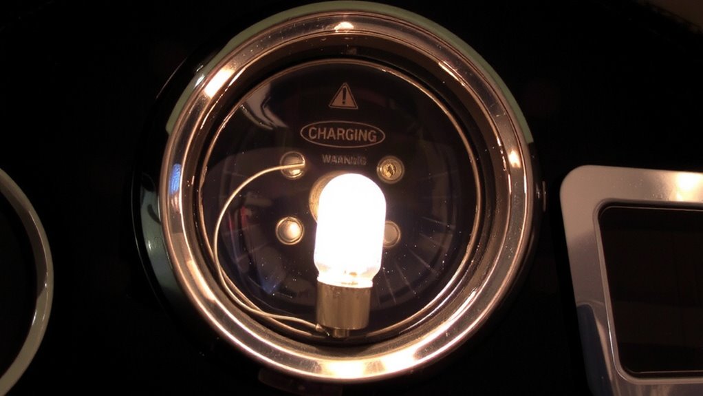
While the charging light seems simple, it’s actually a critical indicator of your vehicle’s charging system health. When you turn the ignition on, battery voltage flows through the charging light circuit, grounding through the alternator’s field coil. This small current lights the bulb, signaling the system is active. The ground connection is essential-if broken, the light won’t illuminate. Once the engine starts, the alternator generates power, matching battery voltage on both sides of the lamp. With no voltage difference, the light turns off, indicating normal operation. If the alternator fails, battery voltage drops, restoring the voltage differential and lighting the warning again. A faulty ground connection or low battery voltage disrupts this balance, causing false warnings or no light at all. You rely on this circuit to reflect real-time charging performance using basic electrical principles-no guesswork involved.
What Tools You Need to Test It
You now understand how the charging light circuit operates, so it’s time to gather the right tools to test it effectively. A digital multimeter is essential-choose one with at least 1.0% voltage accuracy for reliable multimeter accuracy. You’ll need it to measure reference voltages, ground continuity, and driver signal output. Use test leads with sharp, insulated probes to guarantee precise probe placement and avoid short circuits. A wiring diagram specific to your vehicle is vital for identifying the correct pins in the instrument cluster connector. You’ll also need a small pick set to access connectors without damage. A powered test light can verify power and ground, but it doesn’t replace multimeter accuracy. Alligator clips help maintain stable probe placement during dynamic tests. Guarantee your battery is fully charged-low system voltage skews results. For accurate diagnostics, consider one of the Best Car Multimeters that combine precision, durability, and ease of use. These tools, used correctly, let you isolate faults with confidence.
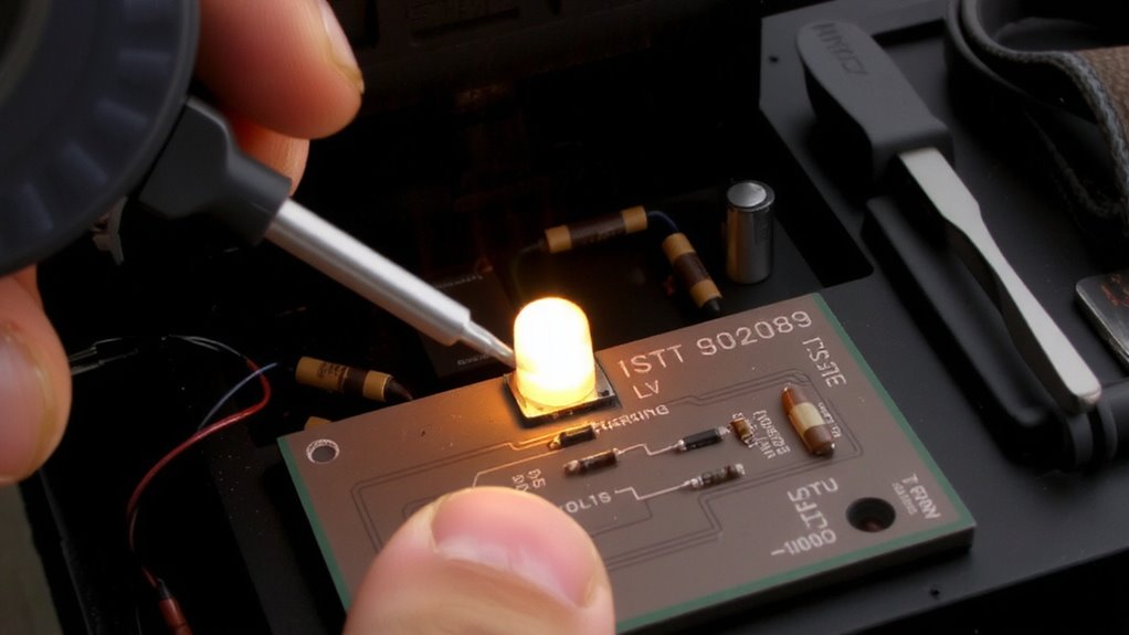
How to Test the Driver Circuit
Since the charging light relies on a driver circuit to control its operation, verifying this circuit’s output is critical. Use a digital multimeter to measure the signal voltage at the instrument cluster’s LED driver pin while the ignition is on. You should see around 0.1–0.3 volts when the engine is off-this low signal voltage keeps the light on. Start the engine; the signal voltage should jump to near battery voltage (13.5–14.8 V), turning the light off. Confirm the ground connection is solid by testing continuity between the driver’s ground pin and chassis. A poor ground connection can mimic driver failure. Use the multimeter’s diode or continuity mode-resistance should be less than 1 ohm. If voltage readings are off and the ground is good, the driver circuit is likely faulty. Always disconnect the battery before probing circuit boards.
Why the Charging Light Lies: False Warnings?
A charging light that behaves unpredictably often points to misleading signals rather than actual generator failure. Electrical interference from nearby high-amperage circuits can induce false voltage readings in the instrument cluster’s control lines. This noise tricks the system into thinking the alternator isn’t charging, even when output measures 13.8–14.4 volts at the battery. You might see the light flicker or stay on despite normal charging performance. Another common cause is a sensor malfunction in the voltage sensing circuit, either at the ECU or within the cluster itself. These sensors are designed to detect differences greater than 0.5 volts from the target range. When they degrade or short internally, they send inaccurate data. The light activates not due to low voltage, but because of flawed input. Diagnose these issues with a multimeter and signal tracing to rule out real charging faults.
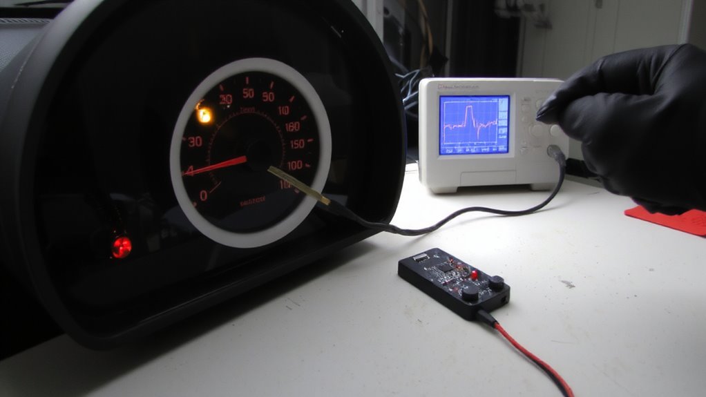
What Your Test Results Mean
What do your multimeter readings really indicate? They reveal whether the charging light circuit functions within expected electrical parameters. A steady 12.6V at rest suggests a healthy battery. Once the engine runs, you should see 13.5–14.8V at the alternator-anything outside this range points to voltage fluctuations. These fluctuations may trigger false warnings in the instrument cluster. If your readings show erratic drops or spikes, you’re likely dealing with circuit anomalies like corroded connectors or failing grounds. Voltage below 12V with the engine on indicates insufficient charging. Over 15V risks damaging electronics. Use multimeter data to confirm if the issue lies in the cluster driver or upstream components. Consistent measurements help distinguish normal behavior from underlying faults, guiding accurate diagnosis without premature part replacement.
Repair or Replace the Instrument Cluster?
How do you know when it’s time to fix the instrument cluster versus replacing it outright? Consider repair if the charging light circuit failure is isolated and components like transistors or resistors are accessible. Surface-mount damage often requires a hot-air rework station with precision temperature control. For widespread corrosion or PCB trace damage, replacement becomes more practical. Evaluate instrument cluster aesthetics-if fading, clouded lenses, or broken backlighting exist, repair won’t restore appearance. Conduct a replacement cost comparison: OEM units may exceed $400, while refurbished clusters average $150–$250. Aftermarket options offer savings but may lack calibration for accurate speedometer or tach readings. Repairs cost $50–$120 labor plus parts but maintain original calibration. If your cluster powers multiple CAN bus messages, verify compatibility. Ultimately, weigh circuit complexity, long-term reliability, and dashboard integration before deciding.
On a final note
You’ve verified the charging light driver circuit using a multimeter with ≥10 MΩ impedance. A proper signal reads 12V when off, 0V when active. Deviations indicate a failing cluster or regulator. Test results are definitive-not symptomatic. If voltage specs fall outside tolerance, replace the instrument cluster. Repairs aren’t cost-effective. Modern clusters use surface-mount logic; rework risks damage. Replacement guarantees calibration integrity and restores accurate alternator monitoring.